Hi,
I have two different designs using the TLV 61224 step-up converter. The input voltage comes from 2 AA alkaline batteries. We need a stable Vout = 3V. The load of the circuit is around 9mA. The first PCB layout works fine. The second layout doesn't work at all. The circuit has some crazy oscillations and the consumed current gets up to 200 mA damaging the TLV61224. Please, help me out with my questions below,
- I'm using a BAS21 diode after the batteries input to prevent the user damaging the TLV61224 when placing the 2 AA batteries backwards. Is this diode necessary in this design? Is this diode causing the circuit to behave erratically?
- The positive output from the AA batteries is located around 2 inches away from the device. Do I need a 47 uF tantalum capacitor?
- Why is this PCB layout not working?
Thank you for your help,
Robert
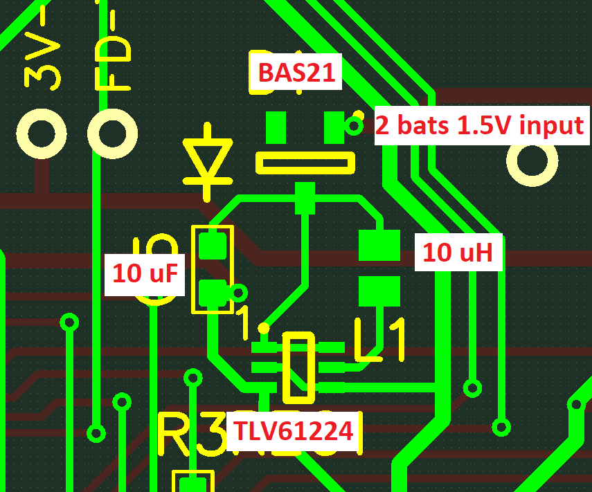
THIS CIRCUIT LAYOUT WORKS FINE
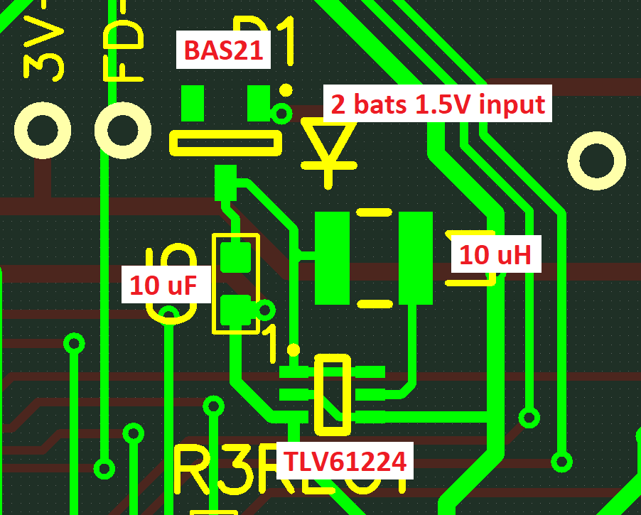
THIS CIRCUIT LAYOUT DOESN'T WORK. IT OSCILLATES CREATING A CURRENT UP TO 200 mA DAMAGING THE TLV61224 CHIP