This thread has been locked.

If you have a related question, please click the "Ask a related question" button in the top right corner. The newly created question will be automatically linked to this question.

BQ77915: battery doesn't charge complete

Part Number: BQ77915
Other Parts Discussed in Thread: BQ24715

Hi,

Hope you are doing good. 

We have 3s2p configuration Li-ion batteries (ncr18650b). We  are using bq77915 IC as BMS in our system. ans bq24715 for our battery charge controller.

We have used bq7791501 part as our BMS.

the battery should be charged upto 12.6V 

The battery stopped charging at 12.35V. we checked the CHG anf DSCHG fets and found out that the dischg fet is on where as the chg fet is turned off. 

from the data sheet table no 9.5 the conditions for fault might be

  1. over voltage fault 
  2. over temperature charge fault
  3. under temperature charge fault.

The battery pack was charging at room temperature. The BP did not reach a temperature of 50 degrees.

coming to over voltage fault condition, we checked the individual cell voltages and measured approx 4.11 V on each cell. which is well within the under voltage range.

We removed the r39 resistor to disable cell balancing condition.

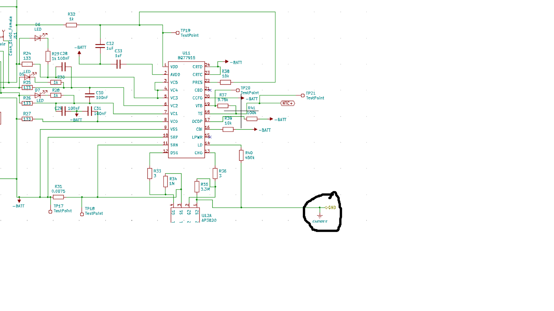
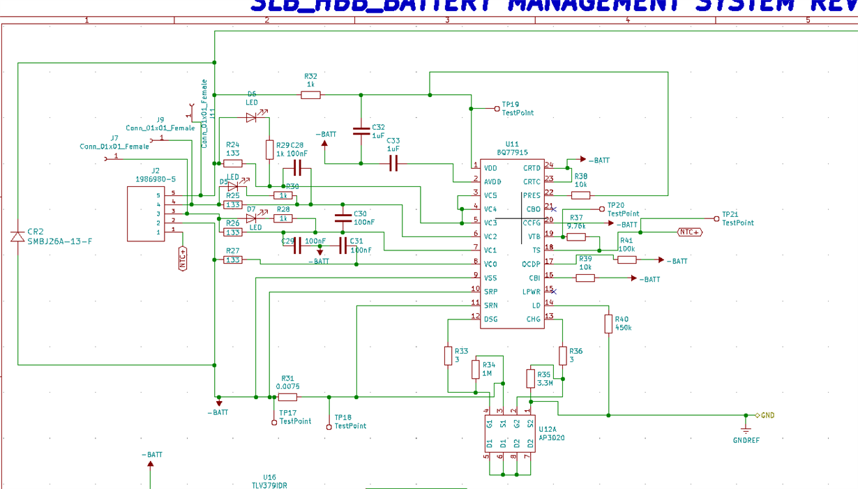
I am attaching the schematic below

We changed the IC to bq7791500 and the sense resistor value to 7.5 mohm 

Once we connected the cell balancing after the battery stopped charging, the led's related to cell balancing D5,D7,D6 are glowing.

the battery pack voltage measures 12.29V  and the voltage across the cells are  4.1V , 4.09V and 4.08V ( the battery back is connected with the help of J2 where Bat + is connected to pin 5. at pin4 we have B1- and B2+ and at pin 3 we have b2- and b3+. and at pin 4 we have battery pack - connected 

We connected load and the fault chgfet turned on and and supplied the load. The battery voltage measured 12.24 V.

i doubt if the condition is over voltage fault condition. but we selected bq7791500 and bq77917501 based on the OV of 4200mV and 4250mV. respectively.

i believe the OV fault condition should occur once the OV threshold is crossed. but we have chgfet off. even when we observe no fault condition.

Can you please help us with this?

Thank-you

Warm regards

Harini Krishna

  • Hi Harini,

    I agree with your analysis. This seems out of range for overvoltage fault, and a temperature fault is rare. A couple of suggestions:

    1. I noticed some of your pins are connected to BAT- instead of GND (like CTRD). This could be nothing, but it would be ideal to connect it to true ground just in case.
    2. What are the values of R33 and R36? They should be 1k and 4.5k, respectively.
    3. I also noticed that Rts (R41) is 100k, it should be 10k. I have seen this create unexpected faults.

  • Hi Shawn,

    Hope you are doing good

    Thank-you for the reply and suggestions.

    I have few questions regarding suggestions

    Thank-you

    Warm Regards

    Harini Krishna

  • Hi Harini,

    I am doing well, thank you! Hope you are doing well also.

    Yes the CTRD and CTRC are for stacking conditions. But the device will trigger fault mode if this pin goes high, that's why we suggest connecting them to a true ground. It is unlikely that BAT- will trigger high, so this is just to be safe. 

    Ah, I see that R41 is the Rocd resistor. Apologies for the confusion. Those values should be fine.

    R33 and R36 seem to be very low. I would suggest using a value closer to the recommended datasheet value. 3.32k should be a better solution.

  • Hi Shawn,

    Thank-you for the reply.

    Can you please give reference calculation for calculating gate resistance?

    Thank-you

    Warm Regards

    Harini Krishna

  • Hi Shawn,

    As suggested,

    • we replaced R33 and R36 values to 1k ohm and 3.32Kohm. ( did not connect CTRC  to true ground). The battery voltage is 12.15V . We tried charging the battery and the battery does not charge.  the Dschg fet is on and the Chgfet is off. We tried connecting 6A load and chgfet is still off. There is no indication of  balancing of cell voltages ( i absolutely see no condition to trigger the OV fault and as you said before, the chances of temperature faults are very remote). This seems to be very strange condition. 
    • We measured the CRTC and CRTD pin voltages with respect to  GND (NOT BAT-) and found both the voltages to be 0.4V. 
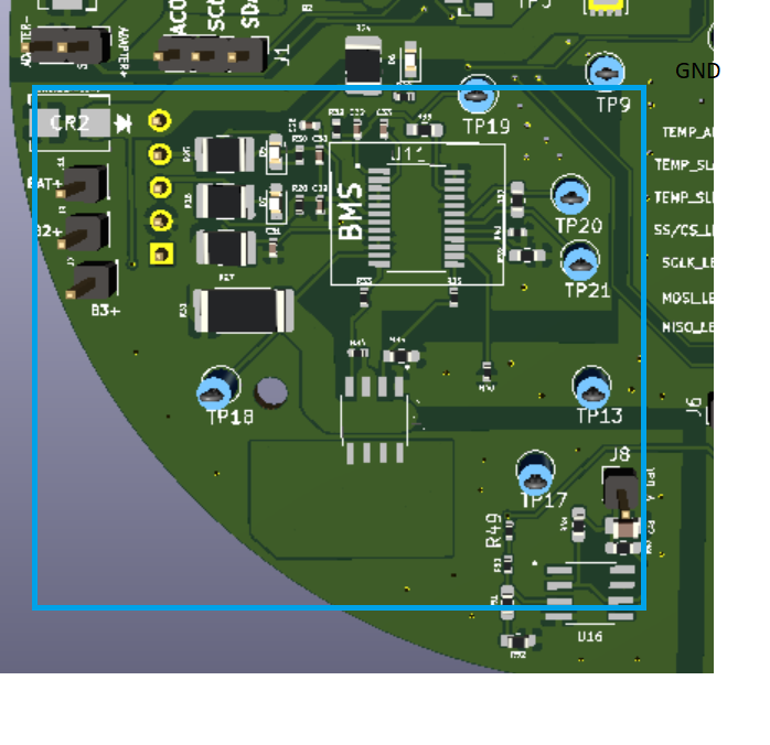
    •  does true ground mean the common ground other than bat-? we have other modules on the same PCB whose ground is isolated from the BMS ground (our case it is bat-) .I am attaching the PCB below
    • The BMS ground (bat -) is completely isolated from the rest of the modules. Does true ground mean the common ground? is it the GNDREF or GND as shown in the schematic below?

    Thank-you

    Warm Regards

    Harini Krishna

  • Hi Harini,

    Have you observed the battery voltage on a scope? Sometimes we see spikes in the voltage that could cause a fault. Is there a way to get the battery voltage low enough to recover and try to charge again? Additionally, have you observed this on just one device or multiple?

    As for GND, it depends on your particular board. I would just make sure that it is a true GND compared to the VDD of the device. Any voltage on these pins could cause issues. 

  • Hi Shawn,

    Thank-you for the reply.

    • we did not check the battery voltage on the scope but we did use multimeter and voltage measurement unit  to measure the battery voltage. There are no spikes in the battery voltage.
    • Once we changed the R33 and R36, the connection of the load is not clearing the fault  condition. the CHG fet is still not turned on.
    • We did have same problem with the same device bq7791501 where the chgfet turned off but the fault got cleared when the load was connected and even before the load was connected, it indicated voltage balancing.
    • should the voltage on CRTC pin and CRTD pin measure 0V?
    • When the load is connected and there is no fault condition, should both chgfet and dschg fet be turned on?
    • As you said the true ground is compared to VDD, the pin VDD on bq77915 is connected to the pack+ and battery+ ( Figure 10-9 from the datasheet). so the true ground is pack- in this case? is it correct or i understood it the wrong way?I am confused a bit regarding true ground.

    Thank-you

    Warm regards

    Harini Krishna

  • Hi Harini,

    • Normally, we like to observe the battery voltage on a scope. It helps us get a better visual of the behavior. I would highly recommend it.
    • If this problem is happening with multiple devices, it is highly likely that there is an issue with the board. If only one device has an issue, it is most likely a faulty device.
    • Yes, the voltage on the CTRC pins and CTRD pins should be 0V.
    • Hypothetically, when the load is connected and there is no fault, the device should turn on both CHG and DSG fets and resume normal operation. 
    • Yes, the VDD of the device is connected to PACK+. In theory, it should be fine to use PACK- and GND. I suggest you double check the values anyway. We have seen odd behavior in the past. This is just to be safe. 

    I would suggest disconnecting the battery and let it discharge a little bit before connecting. This is to ensure the device enters normal operation, and then begin to charge with the new Rchg and Rdsg. It also might be worth a try to disconnect the LEDs from the cell voltage sensing pins.

  • Hi Shawn,

    thank-you for the suggestions.

    based on the EVM of bq77915 we connected all the connections at bat- terminals to pack - terminal

    c32 and c33, c31, c29,c41,c39  connected to  pack - instead of bat-

    IC pin 9 ( VDD), pin 20, (CCFG), PIN 23 CTRD and PIN 24 CTRC are connected to pack- according to the EVM.

    we tried the following test conditions and we observed the followiing:

    • we removed the NTC connection and found out that there is no fault condition occurred. 
    • we tried charging the battery and found out that the old condition of chgfet turning off is still persisting.
    • We connected load to recover fault condition and tried charging it again and the chgfet turns off.
    • We put back all the connections ( the connections shifted to pack -) to  bat- again and observed that the battery is charging without any fault condition occurring and again at 12.2V the charging stopped.  We are using bq7791500 and according to the specifications of the device, the charge voltage is 
    • .We put back all the connections ( the connections shifted to pack -) to  bat- again and when we remove NTC  connections it was showing fault condition and the  battery was disconnected. once the NTC connections were restored, the device returned to normal condition. 

    We have tight deadline for our project and the BMS is behaving very wired. It is always the CHGFET that is turning off.

    Can we connect through call or skype?

    Thank-you

    Warm Regards

    Harini Krishna

  • Hi Shawn,

    We see that at POR the device assumes to be in OV fault condition and will keep the charge fet off. once the cell voltages are below 4000mV for bq77915 , then the chgfet is turned on.  Till the cell voltages reach 4000mV, the chgfet will be turned off?

    Is this condition triggering the chgfet to not turn on when trying to charge the battery pack which is at 12.2V?

    Thank-you

    Warm Regards

    Harini Krishna

  • Hi Harini,

    From your last post, this seems like it may be an issue with the NTC. Could you try to disconnect the VTB pin (leave it floating) and have a 10k Ohm pulldown to ground on the TS pin? This configuration should disable the temperature protection. If the device behaves normally, there is an issue with the NTC. If you are still experiencing odd behavior, the issue may lie in over voltage functionality. 

    In that case, I would recommend disabling the LEDs from the voltage sense pin. It is possible that they are interfering with the voltage calculations. 

    The overvoltage fault behavior is described in the datasheet in section 9.3.2.1. It states: "The device assumes an OV fault after reset, and clears automatically after an OV delay if all cell voltages are below the OV threshold minus hysteresis."

  • Hi Shawn,

    Thank-you for the reply

    in the post 

    it says that the grounds related to bq77915 should be connected to  bat-, but as you mentioned in the earlier post that the  true ground is  which is a compared to the VDD of the device. so Pack -ve  should be connected to the device ground points.

    There is a big confusion when it comes to ground. Can you please tell clearly if it is bat- or pack - to which the grounds if the IC should be connected to?

    Thank-you

    Warm Regards

    Harini Krishna

  • Hi Harini,

    Apologies for the confusion. I agree with the post, the ground connection should be BAT-. VDD is the same reference point as BAT+. 

  • Hi Shawn,

    Thank-you for the clarification.

    Can you please give a reference for the gate resistance calculation?

    We followed the TI document to calculate the gate resistance and the calculated value was 3 ohm which is no where close to the value you suggested.

    Can you please help us with this?

    Thank-you

    Warm Regards

    Harini Krishna

  • Hi Harini,

    Here is a note from one of our designers: "The time constant would be the selected series resistance (Rchg/Rdsg) times the external FET total gate capacitance.  Since 1 time constant (RC) yields the rise time to 63% of the final settled value, that should be about right for a hand calculation of the desired time to turn on the FET.  For fall time, they probably want to use something closer to 2 time constants since the FET is off at closer to 90% of the final settled value."

  • Hi Shawn,

    Hope you are doing good.

    Thank-you for the reply.

    We had a condition where the chgfet was turned off. We measured the battery voltage to be 12.35V and  at  battery+ ( pack+) and pack- to be 11.83V.

    I am a bit confused about charge fet and discharge fet operations.

    From the datasheet i read that only if bot the fets are ON ( CHGET and DSCHGFET) the operation is normal. and at fault conditions based on the fault, either any one of the fets will be off or both the fets will be off.

    in out condition, we measured the voltage at pack+ and pack-  terminals  to be 11. 83V. from the schematic given in the datasheet, i see that the battery - and the pack - are completely isolated when chget is off. how can we still read voltage at pack+ and pack- terminals?

    Why is there a 500mV drop in the readings?

    Thank-you

    Warm Regards

    Harini Krishna

  • Hi Harini,

    This is the correct behavior. You can see this phenomenon described in section 2.4, step 10 of the EVM user's guide. In an overvoltage condition, we keep the DSG FET on so that the battery pack can continue to discharge in order to recover from the overvoltage fault.

  • Hi Shawn,

    Hope you are doing good.

    Thank-you for the reply.

    We watched a video about the cell balancing algorithm on bq77915 device. We are testing both bq7791500 and bq7791501

    We have few doubts regarding the cell balancing

    1. The cell balancing starts at Vstart = 3.8 V ( for both the devices  bq7791500 and bq7791501) and the threshhold is  (Vcbth- Vcbtl) is 100mV. Initially when all the cell voltages crosses Vstart , the cell balancing starts. In step 1 (Vcbtl=3.8 and Vcbth=3.9 V) if any of the cell voltage is above  Vcbth=3.9 V then that cell experiences cell balancing. does the charging process stop while cell balancing?
    2.  When does the lower and upper threshold shift (Vcbtl=3.8V to Vcbtl=3.9 V  and Vcbth=3.9 V Vcbth=4 V)? is it only after the cell balancing in step 1 is completed?
    3. In the video it is  mentioned that the once the cell voltages reached the Vfc threshold ( that is 4.1 V for bq7791501) the balancing will take place only if the cell reads an OV condition ( above 4.2 V for bq7791501). Did I understand it the correct way?

    Thank-you

    Warm Regards

    Harini Krishna

  • Hi Harini,

    1. Yes I believe charging is temporarily suspended while the cells are balancing. However, the balancing is very short.
    2. Yes, the thresholds change only after the cell balancing in step 1 is completed. All cell voltages must be above Vcbtl.
    3. Yes, cell balancing will occur to remove the device from OV fault.
  • Hi Shawn,

    Thank-you for the reply.

    Hope you are doing good. 

    we are using bq7791501 as BMS for  3s2p configuration li-ion NCR18650 batteries.

    1. While discharging the battery we observed that at  8.7 V on the pack and 2.9V on each cell (voltage reading) the battery stops supplying the load. But according to the datasheet, the device should enter UV fault at any of the cell reading 2.8V or below. We had uv fault occurring at one of the cell voltage reading at 2.88V also. 
    2. we observed one more condition where both the fets are turning off at 8.7V battery pack voltage. We have a constant heater load. the load current measured was 5A. from the data sheet it says it can be OCD1, OCD2, SCD, OCC, UTD, OTD, OW faults if both the fets are off. we anticipated it to be OCD1/ OCD2 fault  or SCD fault but we were measuring load current and it read 5A. since the battery was not charging, OCC can be ruled out.  the battery was at room temperature.  We do not see any open wire on the battery pack connections to PCB. We tried to recover the the fault by removing the load, but our application does not support disconnecting the load completely ( we have 3.3V regulator, buck converter and a 5 V regulator along with the heater load at the pack terminals which does not support disconnecting the load completely. keeping the pack terminals floating isi not supported in out application ). can you suggest any other alternative for load removal or clearing the faults where both the fet's are off and the load need to be disconnected to clear the fault?

    Thank-you

    Warm Regards

    Harini Krishna

  • Hi Harini,

    1. This seems odd. The device should not enter UV fault at that level. Please check to make sure no other faults are occurring. Please also measure the voltage directly from the pin of the device.
    2. The device is configured to require load removal to recover from faults. Unfortunately, this cannot be changed. 

  • Hi Shawn, 

    Thank-you for the reply

    Hope you are doing good.

    We are using NCR18650b li-ion battery with 3s2p configuration. i am attaching the datasheet below

    NCR18650B.pdf

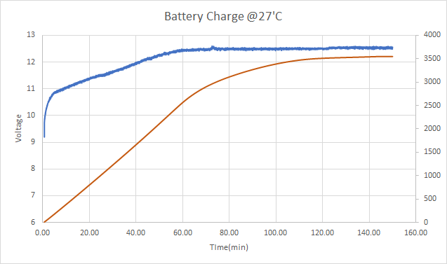
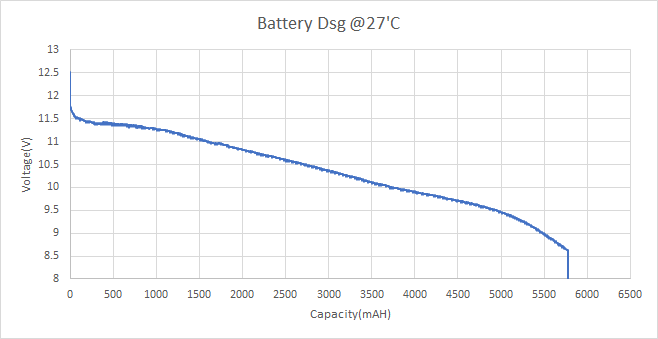
    We plotted the charge and discharge characteristics and found out that the discharge capacity and the capacity are has a lot of difference. the battery is discharging 5774mAh( the battery is not completely discharged) and charging only upto 3548mAh capacity. Please find the attached graphs for  the charge and discharge characteristics.

    We are discharging the battery at 1c and charging the battery at 0.5C

    Why is the  charge capacity very less than the discharge capacity?

    Can you plesase help us with this?

    Thank-you 

    Warm Regards

    Harini krishna

  • Hi Harini,

    I am not an expert on battery chemistry, and therefore I am not the correct contact for this. I can only comment on the behavior of the battery management devices.

  • Hello Shawn,

    Yes, it is odd that the BMS is kicking in at 2.9V and turning off Dsg FET on BQ7791501 which supposed to have a 2.8V UV fault protection. We have measured voltage directly at the PINS they are reading the same values. 

    The observation is it is turning off when one of the cells is reaching at 2.88 or 2.89V situation has not changed. 

    And one more observation, when we tried to measure the voltage across NTC it is showing 0V wrt pack- or common ground. Should it not give some value at 25'C? 

    Our NTC value is 10K at 25'C.

    We are unable to understand why it is turning off at <=2.9V instead of <=2.8V.

    Appreciate any suggestions. 

  • Hi,

    I would recommend going through table 9-5 and seeing what other faults could be occurring. I would also check the value of CTRD.

    The VTB pin (and therefore the TS pin) are not a steady voltage, but rather a series of pulses. That means that the value should be evaluated on an oscilloscope rather than a multimeter. I would recommend checking the functionality on a scope.

  • Hi Shawn,

    Hope you are doing good.

    With bq7791501, we are using a 4.5 mohm sense resistor. 

    to confirm things with you, for a 3s2p configuration, Device :bq7791501  and sense resistor value : 4.5m ohm , the following would be the thresholds

    over voltage (OV) 4250 mV 12750 pack voltage and triggers if any of the cell voltage reads above 4250mV
    under voltage (UV) 2800 mV

    pack voltage: 8400mV and triggers only if any of the cell reads less than 2800mV 

    OCD1(over current discharge 1) 35mV with a 4.5m ohm sense resistor, the discharge current should be 7778mA to trigger a OCD 1 fault

    OCD2( over current discharge 2)

    60mV with a 4.5m ohm sense resistor, the discharge current should be 13333mA to trigger a OCD 2 fault
    SCD( short circuit detection) 120mV if the current value reads 26666mA, then the scd fault shoud be triggered
    OCC( over charge current) 20mV with a 4.5m ohm sense resistor, the charge current should be 4444mA to trigger a OCC fault

    As suggested by you, we did look into table 9.5 from the data sheet and found that for discharge fet to be off, the only possible faults can be  a UV fault or CRTD disabled. as any of the cell is not reaching the UV threshold, the only possible fault would be CRTD.

    As you mentioned in one of the previous posts, the CRTD and CRTC should be connected to ground.We did connect the CRTD and CRTC signals to ground. Aren't CRTD and CRTC pins related to stack configuration?

    What condition may be triggering a CRTD fault in the device?

    Thank-you

    Warm Regards

    Harini Krishna

  • Hi Shawn, 

    We want to measure the battery pack temperature with a adc channel. for SOC estimation of the battery. We want to use the temperature functionality of the device for measuring the temperature of the battery pack.

    Can we use the NTC measurements to read the pack temperature?

    Thank-you

    Warm Regards

    Harini Krishna

  • Hi Harini,

    CTRD and CTRC are only used for stacking implementations, they simply signal to the device that a fault has occurred in one of the upper devices and therefore will immediately trigger a fault. In non-stacking applications, and for the device at the top of the stack, the CTRD and CTRC pins should be shorted to GND. This is to ensure that no stray voltage will trigger a fault. I would observe the pin on an oscilloscope to guarantee there is no unexpected voltage on that pin.

    The NTC measurement should accurately reflect pack temperature. 

  • Hi Shawn,

    Hope you are doing good. 

    We have CRTC and CRTD signals connected to ground.

    when you say to measure signals with respect to battery ground or with respect to  pack negative?

    as we already have both the pins connected to battery negative it would read 0V with respect to 

    could you please tell with respect to which ground the CRTC and CRTD pin voltages need to be measured? with respect to pack - or battery -ve?

    Thank-you

    Warm regards

    Harini Krishna
  • Hi Harini,

    Measure CTRC and CTRD with respect to battery ground, or local battery ground (gnd of the lowest cell in the stack) for stacked devices.

  • Hi Shawn,

    Hope you are doing good.

    Thank-you for the reply.

    in the previous post you mentioned that "The VTB pin (and therefore the TS pin) are not a steady voltage, but rather a series of pulses", can you please tell what is the frequency of the pulse?

    for temperature measurement using temperature functionality of the bq77915 device through ADC channel, how can we make use o the NTC measurements of the battery pack on the bq77915 device?

    Thank-you

    Warm Regards

    Harini krishna

  • Hi Harini,

    It is not a steady frequency of pulses, see this scope shot below:

    The pink line (CH3) is AVDD and the green line (CH4) is VTB.

    If the recommended circuit is followed, the device is set up to read the NTC measurements and trigger a fault if the temperature is unsafe. 

  • Hi Shawn,

    Than-you for the reply.

    I am unable to open the image attached by you in the previous post.

    Can you please attach it again?

    Thank-you

    Warm Regards

    Harini Krishna

  • Hi Harini,

    Sorry about that! Can you see this?

  • Hi Shawn, 

    Thank-you for the reply.

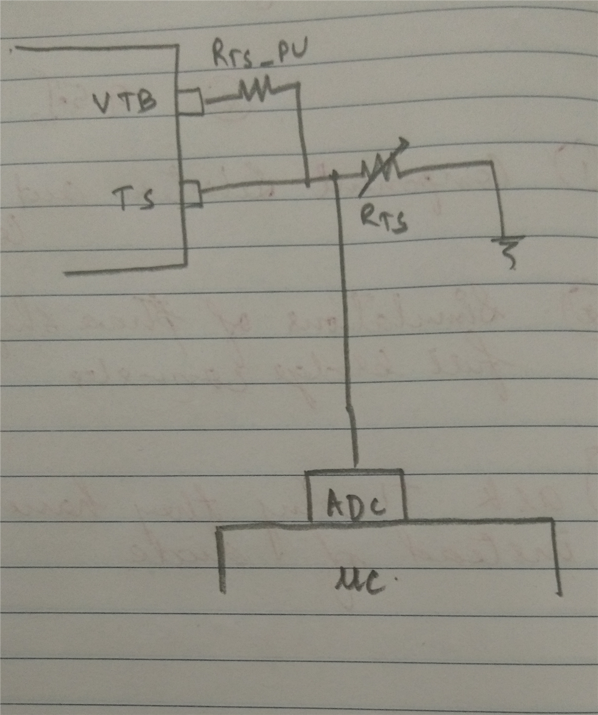
    We want to measure the temperature using ADC channel for battery SOC measurement.

    please refer the figure given below

    we want to measure the temperature of the battery every 1 min to determine the soc. 

    can the temperature of the battery be read as shown in the figure above?

    as you said that the VTB and TS pulses are not steady frequency pulses, how does the bq77915 know when to make temperature measurements ?

    Do you have any suggestions on how to read the battery temperature using NTC connected to bq77 device through an external ADC port?

    Thank-you

    Warm Regards

    Harini Krishna

  • Hi,

    I am not sure of the exact workings of the device, and it is most likely part of our protected IP and therefore I would be unable to share the exact details. I do know that in general, the device measures the voltage at both the VTB and the TS pin and comparing them. This is outlined in section 10.1.1.5 of the datasheet. As for if your configuration will work, I am not sure. I can only give advice on how the battery protection chips will work.