This thread has been locked.

If you have a related question, please click the "Ask a related question" button in the top right corner. The newly created question will be automatically linked to this question.

WEBENCH® Tools/LM5176-Q1: About average current limit and soft start capacitor capacity

Part Number: LM5176-Q1
Other Parts Discussed in Thread: LM5176, , INA220

Tool/software: WEBENCH® Design Tools

Hi,

I use the LM5176(-Q1) device.

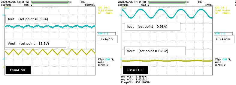
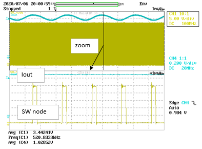
Although the average current limit function is used, the output will oscillate when the output voltage reaches the preset 1/3 voltage as shown below.

(The set current value is 0.98A, but it will be less than this when oscillation starts.)

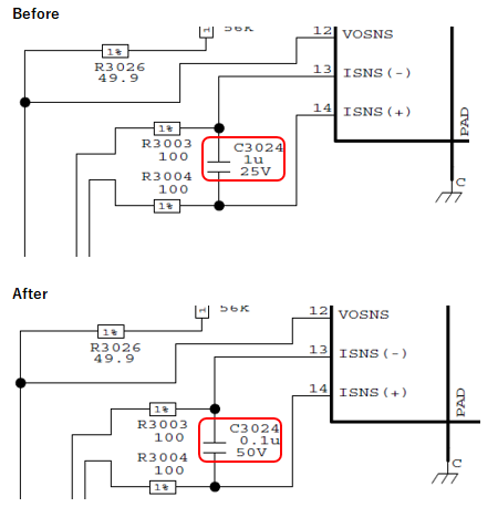
It improves by changing the soft start constant (Css) from 4.7nF to 10nF.

Even with the E58 cell of the attached LM5176 quick start tool,4.7nF cannot be selected (N/A),

so is there a lower limit for the soft start constant (Css)?

200706_LM5176 Buck-Boost Quickstart Tool r1.0.zip(Attachment of the above figure)

I understand that the average current limit uses the functionality of the soft start block.

Therefore, the soft start constant (Css) is made small (I want to use 4.7nF) to improve the response of the current limit.

However, since the oscillation operation is observed during the average current limiting operation as described above,

please tell us the recommended range of the soft start constant (Css) when using the average current limiting.

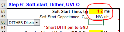
On the attached Quick Start Tool, if the soft start time is 1.3ms or more (Css>=8nF), it will be displayed as no problem.

Best regards,

  • Hello t-naka,

    The softstart time cannot be set shorter than the internal softstart of 1.28ms. In your file you set it to 1.2ms.

  • Hello Brigitte

    Thank you for your reply.

    >The softstart time cannot be set shorter than the internal softstart of 1.28ms. In your file you set it to 1.2ms.

    Where can I find this time constraint in the data sheet?

    I would like to know the details.

    Even if the minimum soft start time of 1.28 ms is satisfied, the output voltage oscillation at current limit is

    not released as shown in the figure below. Is there a way to improve this?

    The load in this case is an electronic load and is set to have a constant resistance value.

    (If the soft start Css constant is increased, the above oscillation frequency also decreases. Is it a trial and error?)

    Best regards,

    t-naka

  • Hello t-naka,

    Please share your schematic. I wonder if the average current limit and the peak current limit are working against each other in your setup.

  • Hello Brigitte

    I will send you the circuit diagram.

    The average current is set to typ 0.98A and overcurrent protection is set to 1.4A.

    (Oscillation frequency: Ext 520kHz, input: 24V, output: 15.3V)

    LM5176-Q1_sche.pdf(PDF of the above circuit diagram)

    The oscillation of the SW node waveform is not stopped even at the output current peak of ch4 (it has not entered the overcurrent protection operation).

    Best regards,

    t-naka

  • Hello t-naka,

    It seems that the output voltage set with the resistor divider is 19V.

    Please let's check if the design is stable when no average current limit is used. Please short the resistor on the output and review the circuit behavior.

  • Hello Brigitte

    >It seems that the output voltage set with the resistor divider is 19V.

    Sorry, As shown in the figure below, about 2.64V is applied by the DAC to the middle point of the resistor voltage divider, so the actual output voltage is about 15.8V.


    >Please let's check if the design is stable when no average current limit is used. Please short the resistor on the output and review the circuit behavior.

    If the current detection resistor (RSNS) is shorted with solder as shown in the lower left figure,

    stable operation will be achieved up to about 2.2A, but if it exceeds 2.2A, the central figure

    and intermittent oscillation will occur. If the load increases, deeper intermittent oscillation

    will occur as shown in the right figure. However, the operation is stable.

    Although RSNS is completely short-circuited by the solder, SW operation is continuing and the output voltage

    is decreasing according to the load. This looks as if the average current limit function is working. Is this normal operation?

    Best regards,

    t-naka

  • Hello t-naka,

    I expect that in this case the peak current limit set with the sense resistor to GND is operating, not the average current limit. With shorting the resistor in the output, you disabled the average current limit.

    Could you please check the inductor current in the above measurements? With the used sense resistor, the peak current should be around 2.6A in the inductor.

  • Hello Brigitte

    >I expect that in this case the peak current limit set with the sense resistor to GND is operating, not the average current limit. With shorting the resistor in the output, you disabled the average current limit.

    I shorted both ends of RSNS again and measured it, but it became the average current limit operation.

    As shown in the figure on the left below, the differential voltage of the IC pin (ISNS+/ISNS-) is almost 0V.

    In addition, the peak current of the inductor(coil) was about 2.6A as you pointed out (right figure below).

    Are these behaviors correct? (I'm worried that even if both ends of RSNS are short-circuited,

    the average current limit operation will be activated.)

    Best regards,

    t-naka

  • Hello t-naka,

    If you short ISNS+ to ISNS-, the average current limit is disabled. The average current limit is only active when there is a voltage of about 50mV between them.

    The 2.6A current limit is the limit set by the 39mohm resistor connected to CS+ and CS-.

  • Hello Brigitte

    >If you short ISNS+ to ISNS-, the average current limit is disabled. The average current limit is only active when there is a voltage of about 50mV between them.

    Sorry,

    The cause of the average current limit operation was found. Since it was set to No Hiccup mode with the MODE pin,

    it was operating in average current.When Hiccup mode was enabled, it became intermittent operation instead of average current operation.

    However, the oscillation phenomenon during the average current limit is not solved.

    As a result of confirmation here, when the filter capacitor between ISNS(+) and ISNS(-) is changed

    from 1uF on the LM5176 data sheet to 0.1uF, the oscillation phenomenon at the average current limit disappears.

    The above values were determined with reference to the INA220 data sheet. Is it applicable to the LM5176-Q1?

    The filtering band is 50kHz (1/2*Rfilter*Cfilter), and the SW frequency is 500kHz or less, so I think it can be used.

    Best regards,

    t-naka

  • Hello t-naka,

    I think this is a good solution. Please excuse that I overlooked that the bandwidth of the peak current limit and the bandwidth of the average current limit is very close to each other. With the reduction of this cap you get them about 1 decade away from each other.

    In general I would recommend to make the average current loop slower than the peak current loop, but I do not expect a big problem, if you make it the other way around.

    If you still have the ability to change the layout, I would as well recommend to split the output capacitance and place the average current sense resistor in the middle of these capacitors. This should minimize the noise introduced from the converter as well as from the load.

  • Hello Brigitte,

    >I think this is a good solution. Please excuse that I overlooked that the bandwidth of the peak current limit and the bandwidth of the average current limit is very close to each other. With the reduction of this cap you get them about 1 decade away from each other.

    I also overlooked the above contents.

    Unknowingly, the peak and average control loops were close to each other, causing the problem this time.

    I learned a lot.

    Thank you for your consultation.

    Best regards,

    t-naka