Other Parts Discussed in Thread: TPS62745
Hi!
I use TPS62743 in li-ion battery-powered application. Supply current 12uA in sleep mode and 8mA in active mode. Vout programmed to 3.0V.
Cin 4.7uF Murata GRM188R61E475KE11
Cout 10uF Murata GRM188R61A106KE69
L 2.2uH Murata LQM2MPN2R2MG0
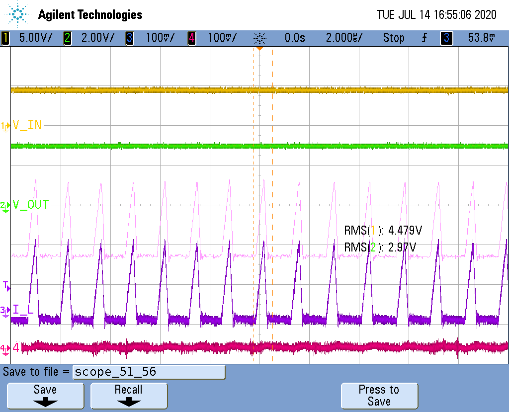
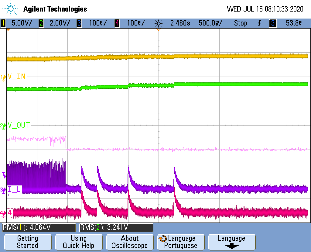
I see that at Iout less than 5 mA device doesn't regulate the output voltage.
Vin=3.8V Vout=3.2V,
Vin=4.0V Vout=3.4V and so on.
I see no pulses on SW pin. I see pulses on SW pin and regulated Vout if input voltage between 3.3 and 3.6V.
If Iout greater than 5mA device works properly.
On screenshots Yellow - Vin, Green - SW
Vin = 3.6V
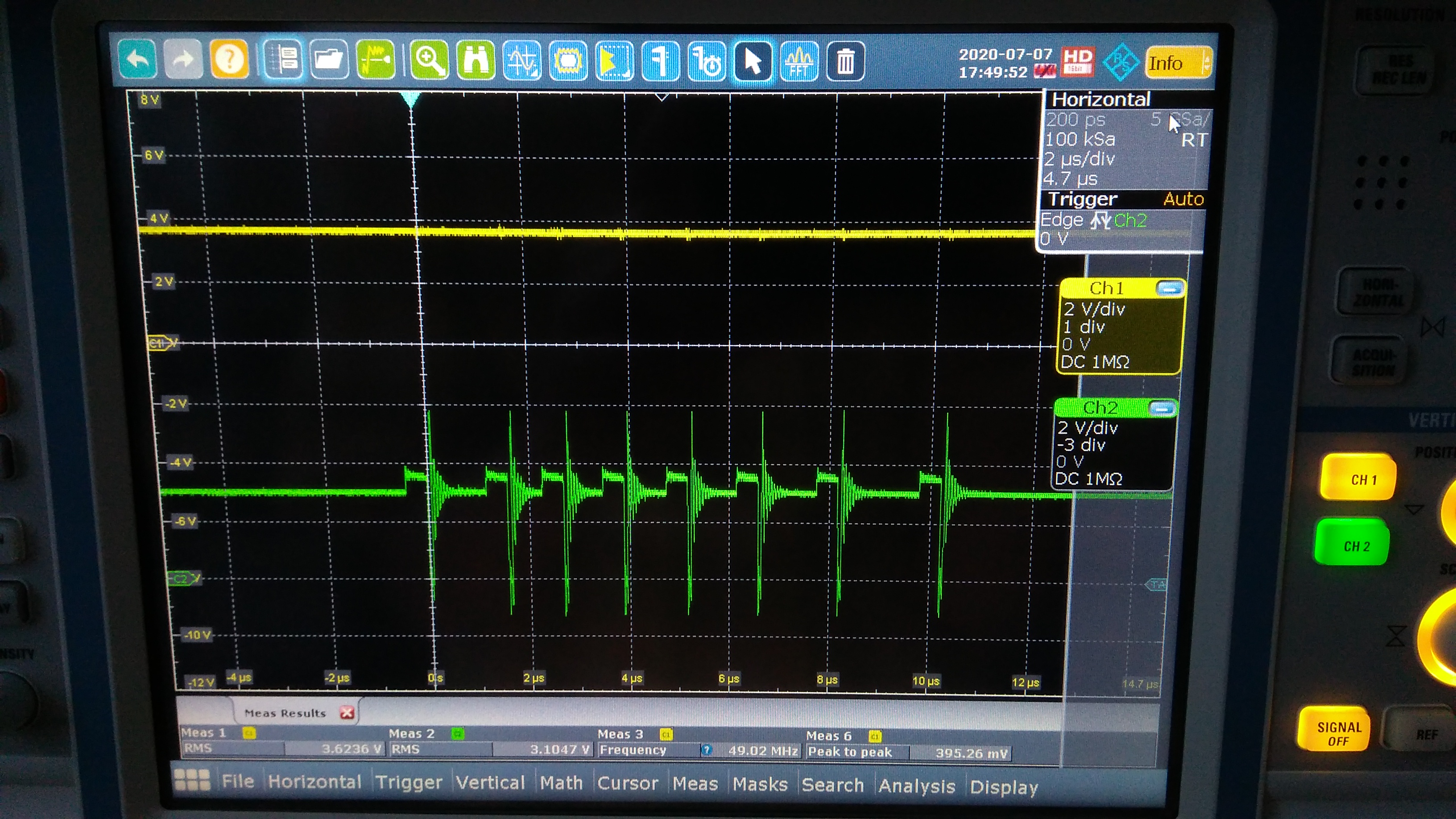
Vin = 4.0V