Hi team!
I've a issue with the current biasing point of the current transformer let me explain as follow in the picture below.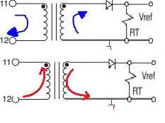
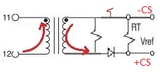
As you can see the normally operations is drawed with the blue arrows the current is coming from the dc link and is going from 11 to 12 primary and in the secondary is going from the dotting point to the rectifier diode.
But what if the current is going from 12 to 11..
Is the secondary side good designed in the first picture or do you suggest the design in the picture below or maybe another suggestions?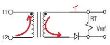
Thank you team!