This thread has been locked.

If you have a related question, please click the "Ask a related question" button in the top right corner. The newly created question will be automatically linked to this question.

bq27510 UpdateStatus does NOT = 2 error, please help

Other Parts Discussed in Thread: BQ27510, BQ27510-G2, BQ20Z80, BQ27501, BQ27500

Hello

I am using a bq27510 and the bq easy gas gauge evaluation system to create the Golden file,  and I have done the learning cycles correctly and have waited the correct times for each cycle. However, when the 4th step is finished, I get an error message saying: "Dataflash.GasGauging.State.UpdateStatus does NOT = 2. Impedance track learning cycle was not completed correctly. Verify procedure and repeat."  What am I doing wrong??

  •  

    Edna,

    This (unfortunately) happens all the time, and is difficult to debug without completely understanding what is going on.  Therefore, I apologize in advance for the treatise, but for the record, let's cover the following:

    1) Basics of how the Impedance Track algorithm works (feel free to skip this if you are confident that you understand it)

    2) Information that the gauge presents to you on the current status of IT

    3) How a learning cycle works

    4) What can go wrong, how to diagnose it, and how to solve it.

    OK,

    (1) Impedance track in a nutshell: if you want more information, please ask me or consult: Theory and implementation of Impedance Track battery fuel-gauging algorithm...

    There are two primary pieces of information that we really want from a gauge: State of Charge, and energy/coulombs remaining.  Energy/coulombs remaining tells us how long we can continue to run, and state of charge tells us what this is as a percentage of the total battery capacity. 

    The gauge uses a combination of open circuit voltage (OCV) measurements and coulomb counting to determine the absolute state of charge, and the IT algorithm determines how much energy we can pull out of the battery before it dies.

    Right now, we are more concerned with the absolute state of charge determination.  While the battery is relaxed, the gauge measures the voltage and determines state of charge based on this value.  When the battery starts charging/discharging, it then uses coulomb counting for relative calculations.  When the charging/discharging stops, the gauge waits for the cell voltage to relax and then measures the OCV to determine absolute SOC again.

    To determine remaining energy/coulombs, the gauge has an internal picture of the battery and runs a simulation of the battery voltage/impedance from its present state to end of discharge.  To do this, the gauge needs to know the battery voltage versus state of charge (the chemistry ID), and the battery impance versus state of charge.  We must learn the latter by performing a learning cycle.


    (2) The information that the gauge presents about IT

    Data RAM Control/Flag Bits:

    VOK: "Voltage OK for QMax Update": This bit basically tracks when the gauge measures the battery's voltage.  This bit is generally set when you start charging/discharging, and is cleared when you have stopped discharging, the gauge has detected that the battery voltage has stabilized, and the gauge has taken the OCV measurement.  It is a good way to track when OCV measurements occur.

    QEN: Qmax Update Enable.  This should be 1 during your learning cycle.

    RUP_DIS: Resistance update disable.  This bit may be set for a number of reasons that we will discuss.  When it is set, this means that the gauge is unsure of its current state and calculations and is not confident enough to update the battery resistance tables with its presently measured data.  It is cleared when you get a good OCV measurement, as the gauge can know the absolute state of charge based on this value.

    FC: Full Charge bit.  This flag indicates whether or not the gauge detects the battery as "full"

    Data Flash:

    UPDATE_STATUS: This data flash value contains the current status of the learning cycle is: it can be 0, 1, 2.  I will discuss what this means below

    Qmax Cell 0/1: This data flash value contains the max battery capacity in mAH.


    (3) How a learning cycle works:

    The learning cycle starts with a discharged, relaxed battery (battery voltage is stable and at low (~3.0-3.3V) voltage).  Upon running IT_ENABLE, the gauge measures this voltage and identifies what state of charge this is associated with using your chemistry ID. 

    At this point, RUP_DIS is cleared, VOK is set and QEN is set.

    Now, you charge the cell to full (note that the GAUGE has to detect that the cell has a full charge and set the FC bit, this is a major tripup point, and I will go over it later).  Once the charge stops and the cell voltage relaxes again at high (4.1-4.2V usually) voltage, the gauge takes another voltage measurement and looks up what state of charge it represents.  Now that we have 2 known states of charge and the # of coulombs between them, the gauge calculates the maximum capacity (qmax) of the battery.

    At this point, UPDATE_STATUS goes to 1, indicating that we have successfully completed the first state of the learning cycle.  QMax Cell 0 is updated to the actual value.  VOK is cleared.

    Now, you begin discharging at C/5.  When this happens VOK should be set again.  As you discharge, the gauge should update the Resistance Tables in the Data Flash every 11% SOC or so and then more rapidly below 20%.  During this time, the gauge is measuring the battery impedance at each state of charge and storing it in these tables.  When you reach end of discharge and remove your load, the battery will relax again to a low (~3.0-3.3V) voltage.  The gauge will wait for this relaxation to occur (this takes much longer at low state of charge than high state of charge), and then it will take an OCV measurement.

    At this point, VOK will be cleared, QMax cell 0 will be updated.  The gauge will also check to see if the resistance table was properly updated.  If it was, then it will set UPDATE_STATUS = 2. 

    Now that we know how it SHOULD go, lets talk about how things can mess up.


    (4)To diagnose a failed learning cycle, it is critical that you set EVSW to log the Data Ram during the Cycle every ~5-10 seconds.  It is also advisable to autoexport the Data Flash on a less frequent basis (every ~1-10 mins).  This way, you can look at all of the information to determine the point of failure.

    Here are the most common points of failure:

    (a) Make sure that the battery is at low SOC and relaxed when you run IT_ENABLE.  This is generally not a problem, but it is important enough that it should be mentioned.

    (b) When you charge, make sure that you the gauge detects the "full charge" condition.  If after the learning cycle, UPDATE_STATUS has not even been updated to 1 (i.e. it is still 0), then this is likely your problem.  The gauge detects the full charge condition with 3 criteria:

        (i) Battery voltage is within 0.1V of the "charging voltage" as defined in bqEASY.

        (ii) Battery current is below "taper current" as defined in bqEASY.

        (iii) Battery current stays below this "taper current" and above the "quit current" for over 40 seconds.  This means that the battery must be charging with a significant current below the "taper current" for almost a minute.  This gets most people.  If the charger cuts off before or just after the current drops below the "taper current" as indicated in bqEASY, then the gauge does not detect the "full" condition. 

    (c) When fully charged, make sure you wait long enough for the VOK bit to be cleared.  This is generally 2 hours.  Logging dataRAM will show whether or not this has occurred.  UPDATE_STATUS will stay 0 if this does not happen.  If VOK is never set, then this means that you did not start with an empty battery, you did not fully charge the battery, or your charge cycle was messed up in some way (see (g) for charging advice).

    (d) When you start discharging, make sure that the VOK bit gets set.  The gauge has a data flash parameter "DSG Threshold" that determines the minimum current needed to enter the "discharge" state.  If you discharge with less than this current, the VOK bit will not be cleared.  The gauge will never go into the "discharge" state, and the Ra tables will never be updated.  UPDATE_STATUS will be '1'.  Either decrease "DSG Threshold" in the Data Flash, or increase your discharge rate.

    (e) When you discharge, the Resistance table is NEVER UPDATED. If you run a learning cycle and your Data Flash log shows that the Resistance Table never changed, this generally indicates that your discharge load was too light.  The gauge needs to measure a significant voltage drop across the internal battery impedance before it can measure said impedance.  If the load is too light, the measurement fails, and you never get any resistance table updates.

    (f) When you discharge, the Resistance Table may update for a while, and then stop.  When this happens, RUP_DIS is set.  This generally indicates that your Chemistry ID choice is incorrect.  This means that the gauge has measured a resistance value that just doesn't make sense (i.e. is negative).  If you re-run your chemistry cycling or contact us, we will help you get a correct value.


    (g) General Charge/Discharge Profile Advice: Most learning cycles fail because there is something generally wrong with the charge/discharge profile.  Here are some tips:

      (i) Don't charge forever:  Most people don't have a battery cycling automation setup, so they think they can hook a bench power supply to a battery overnight and have this be the charger.  This DOES NOT work.  The system does follow a CC/CV profile, but there is no cutoff.  Therefore, when the gauge recognizes full charge and tries to take an OCV measurement, it actually just measures the supply voltage and messes everything else up.

      (ii) CC/CV charge profile: In line with the above, make sure you use a CC/CV profile charger with reasonable values. (C/2 Fast charge rate, C/100 to C/10 taper current)

      (iii) continuous charge profile: While not strictly necessary, it is very advisable to make sure that your charging profile is continuous.  If the charging cycle stops, then the cycle is likely to fail.  If the battery discharges for any reason during this time, the cycle will absolutely fail.

      (iv) After Charge, Relax at least 2 hours with NO load/charger: Make sure you wait long enough to see VOK.  2 Hours is generally enough

      (v) Discharge C/5 Constant Current: Make sure you use a C/5 current.  This is a "sweet spot", and there can be some error.  However, if your current drifts too high or too low, the cycle can fail.  Too low is around C/10, Too high is around C/3 to C/2.  Smaller cells (<800mAH) are much less forgiving in this regard.

      (vi) Continuous discharge:  This absolutely necessary.  If the discharge ever stops before reaching your terminate voltage, the cycle will fail.

      (vii) Termination voltage: Make sure that when you reach terminate voltage, you remove the load and let the cell relax.  If you keep the load attached to the battery and allow the battery voltage to drop well below terminate, then not only will your learning cycle fail, you will also damage your battery.


    Whew.

    OK, so this should give you some place to start.  The key takeaway is this: Log both Data Ram and Data Flash during your learning cycle!  it will save you LOTS of time when something fails.

    Look for the above breadcrumbs in your logfile, and correct your cycle/configuration accordingly.  This is everything I can think of, but there can always be something I forgot to add/haven't seen, so if you have any questions, please don't hesitate to ask. 

    Let me know if this helps,
    Charles


  • Charles,

    Although I am after successful learning cycle, I think it would be really *great* if these tips could be written down and published along other application notes for bq257xx.

    Also, I have one question regarding the FC bit. "Configuring the bq27510-g2 Data Flash" says that if "FC set %" is set to anything other than -1 (by default it is set to 100%), then the combination of Taper Current, Min Taper Capacity, Taper Voltage and Current Taper window is not used. Is this true for the learning cycle?

    Thanks!

  • Hello Charles, I having the same problem as Edna, I have cyled 3 times and i´m still getting the same error  UpdateStatus does NOT=2.  According to the battery manufacturer the battery chemistry is LiCoxNiyMnzO2,  which i can´t find in the chemistry selection, so i did a chemistry cycling and obteined the code id 0206 ( this might be the problem).  Is there a code ID i can use for this kind of battery? or,  do i have to do a chemistry cycling again?.  


  • Hello Charles,

    I have a question about your comment:  "(vi) Continuous discharge:  This absolutely necessary.  If the discharge ever stops before reaching your terminate voltage, the cycle will fail."  Are you absolutely certain about this?  Just to note here, I use the bq20z80Av1.10 in my designs, and not the bq27510. Is this something specific to the IT-algorithm updates in the learning cycle (generally), or is this specific to the bq27510 here?

    I have had many issues when using a constant discharge profile (from a fully charged state, all the way down to terminate voltage), and the resistance tables will only update at the end of discharge, and not every 11% (roughly) discharge steps in SOC.  When doing this, Update Status never changed to 06.

    So to address this, what I have done in the past is to let the cells relax (so stop discharging) for approximately 10 minutes (basically as soon as you notice the R_a tables update) every 11% depth-of -discharge (and every 3% DOD roughly, when SOC is below 10%), the resistance tables will update accordingly, as they should be during these DOD percentages.  As a result, Update Status would change to 06, and everything has now been working for quite a while.

    -apostolos


  • Apostolos,

    You are correct, I was perhaps a bit overzealous in my comment.  It is possible to have a discontinuous discharge and still successfully learn.  However, this process generally has a much higher failure rate and is much more difficult to debug.  The bq27510 does have significantly different firmware from the bq20z80.  With the bq27510, there is less control over the gauge functionality, and less debug information exposed.

    If you aren't getting a resistance update and RUP_DIS is not being set, we generally recommend increasing your load to allow the gauge to get a stronger measurement of the voltage drop due to impedance.  However, periodically stopping discharge to allow a relaxation can achieve the same effect, as you have found.  I have not tested this method personally, but it sounds reasonable.  My only concern here is that with the bq275XX series gauges, I would be concerned that the gauge would prematurely terminate the learning cycle.  As I mentioned, the 510 does not have as much configuration or debug control, so if something does go wrong, it would be more difficult to determine the root cause and subsequently control your cycle well enough to be successful in the future.

    As a result, we recommend the constant current discharge mainly for simplicity's sake.

    Thanks,

    Charles


  • Hector,

    I apologize for the delay in response.  It is very likely that you are having some issues with your chemistry.  Can you remember what the calculated error was in your measurement? 

    Also, did you use the bqEASY method of determining chemistry?  As a general rule, we recommend that customers use the MathCAD script if possible.  This script should be available on all bq275xx web pages.  If you can't run this file, contact me directly, and I'll try to support you that way.

    Thanks,

    Charles

  • Dear Charles,

    I'm experiencing problems with learning cycle too :-(

    My battery is a 3700mAh Li-Po cell, so learning cycle are quite long ...I only want to configure the bq27501 for this cell.

    I have fixed some errors by reading your previous message that is very explicit. Meanwhile, learning cycle always finish with this message : Dataflash.GasGauging.State.UpdateStatus 0 does NOT = 2. Impedance track learning cycle was not completed correctly for both packs. Use Pack A and repeat. I've check registers and I don't understand what is wrong... maybe chemistry ? I have process to a chemistry cycle with less than 1% error but I wonder if the bq27501 keeps this parameters when learning cyle fail?

    upload file is not working (2Mo zip file), can i send it to you by email, this zip contains log and dataflash export.

    Best regards,

  • Hi Julien,

    If you only plan to use one battery type then I would recommend that you use bq27500 (or better yet, bq27510) instead of bq27501.  Because bq27501 is designed to store two different battery profiles, the creation of a golden image with bqEASY is trickier and requires that you repeat two learning cycles (one for each profile) and correctly switch profiles for each one by using the resistor ID (RID), which is also tricky to configure.

    Also, what is your current during the learning cycle?  It must be at least C/10 (3700/10 = 370mA) for a succesful learning cycle.  However, your problem is probably not related to that but rather to the challenge of running two learning cycles to get the two Update Status registers equal to 02.

  • Hi,

    I have try to "fake" the second cell by configuring the second RID with an other resistance value. I've made the second cycle with this resistance instead of the RID cell.

    I think it was working because QMax cells values were both modified.

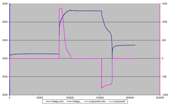
    Here is a graph (for the second cycle) :

    Discharge current is about 700mA. 


    Unfortunately our target PCB is already in production :-(  But I will try to change the chip on a PCB to check if it is not working better with a bq27500.


  • I'm glad that worked for you.  It's a good solution. 

    Another trick you could try is to use File->Export your gg file in the DataFlash screen, then edit the gg file by copying the learned settings from the Pack0 profile to Pack1, then using File->Import and clicking Write All.  That way you will have the same learned values for both profiles and you can have Update Status = 02 for both.  Then bqEASY should let you proceed without physically learning the second profile.

  • I didn't work complety because I still have the error message "UpdateStatus does NOT = 2".

    I will try to copy manually data tables, does Update status will be set to 2 automatically or should I do something else?