This thread has been locked.

If you have a related question, please click the "Ask a related question" button in the top right corner. The newly created question will be automatically linked to this question.

TPS79101-EP: TPS79101 BYPASS CAPACITOR SELECTION

Part Number: TPS79101-EP
Other Parts Discussed in Thread: MSP430F5528

Hi,

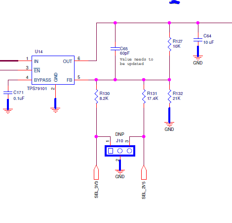
I am planning to use TPS79101 for my project and I have a requirement to change the supply output between 1.8/2.5/3.3V.

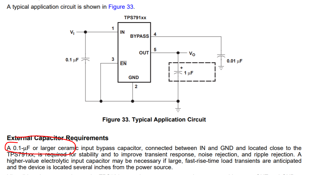
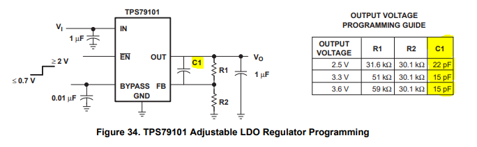
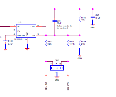
I am already using a MSP430F5528 MCU and hence I plan to keep R1 constant and R2 changing as shown below. In the External Capacitor Requirements section, bypass capacitor is changing with respect to VOUT.

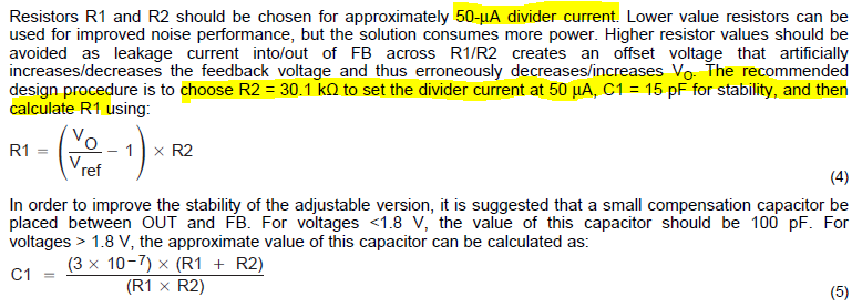
With respect to the resistors selected, I need to change the bypass capacitor selection to 44p, 60p, 80pF for 1.8, 2.5, 3.3V respectively. Is there a way to keep one capacitor for all three voltages so that the voltage selection will be automatic. Kindly advice.

  • Hi Radhakrishnan, 

    I could not see the picture you attached, please reupload your picture using the add picture button instead of directly paste into the text area. 

    Upon checking the datasheet, a >0.01uF bypass cap is recommended. Where did you get the recommendation of having different bypass for different output options? 

    Regards, 
    Jason Song

  • Hi,

    Instead of mentioning about the FB cap, I have put up "bypass cap".

    My question is for FB - OUT capacitor selection. I need to configure the LDO for 1.8 / 2.5/ 3.3V and I have selected R1 and R2 accordingly. Now for the given output voltages, C1 value is changing.

    With respect to the resistors selected, I need to change the FB -OUT capacitor selection to 44p, 60p, 80pF for 1.8, 2.5, 3.3V respectively. Is there a way to keep one capacitor for all three voltages so that the voltage selection will be automatic. Kindly advice.

    Please find the attachment. I am planning to use the 

  • Hi Radhakrishnan, 

    I would suggest you using the one calculated for the 2.5V which is the one in the middle. Having a feedforward cap can improve AC performance, as long as it's in the accepted range, the absolute value could vary. 

    You may find more details in this app note. 

    https://www.ti.com/lit/an/sbva042/sbva042.pdf?ts=1595030004797&ref_url=https%253A%252F%252Fwww.google.com%252F

    Regards, 
    Jason Song

  • Hi Jason,

    Still I have some couple of doubts in this topic.

    Datasheet specifies as shown below that R2 need to be constant and R1 variable keeping the divider current to 50uA approx. But for our application point of view, I need to vary R2 in order to change the output voltage. 

    In our schematics, we are varying R2 instead of R1 and C1 is taken with respect to 2.5V(as you have suggested). We would like to know, with respect to the values we have selected as below, we are not compromising on the noise performace and PSRR of the LDO as it is going to be used in noise sensitive RF applications.

    These values don't adhere to the 50uA feedback current. So please confirm if it compromises on the LDO noise performance and  PSRR.

    Kindly advice.

      R1 R2 C1
    1.8 10k 21k 60p
    2.5 10k 21k || 17.4k 60p
    3.3 10k 21k|| 8.2k 60p
  • Hi,

    Please help answer the above question to close our design.

  • Hi Radhakrishnan, 

    The resistor dividers used in your schematic all have higher than 50uA of divider current and they are good. 

    Regards, 
    Jason