Other Parts Discussed in Thread: LM27313
Hi team,
We would like to use LMR62014 to replace APW7137. We removed the R31.
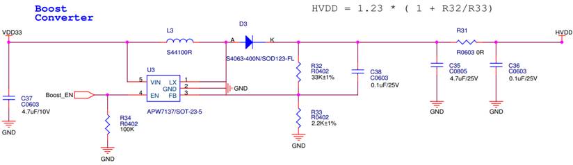
The original C38(Cf)=0.1uF I measure the Vout and sw node. It's ok to me.
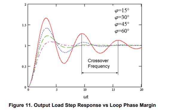
But I look feed forward compensation design in datasheet. Cf = 1/(2*pi*33k*6k)=0.8nF
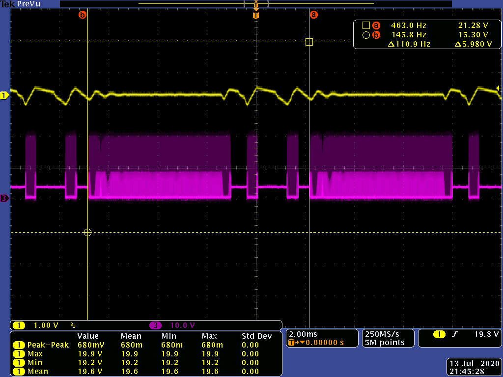
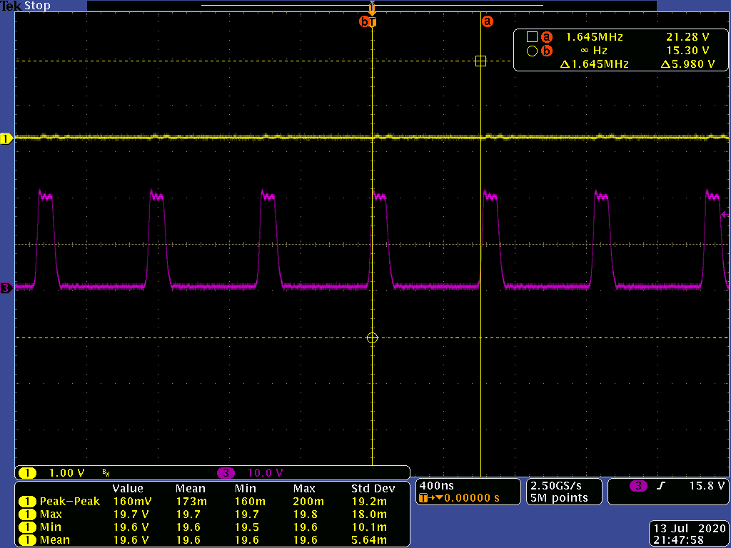
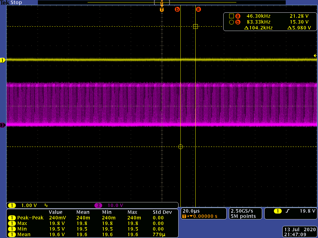
So I replace 0.1uF with 820pF but there is low frequency noise in no load. And noise could be eliminated when adding small load(20mA)
no load
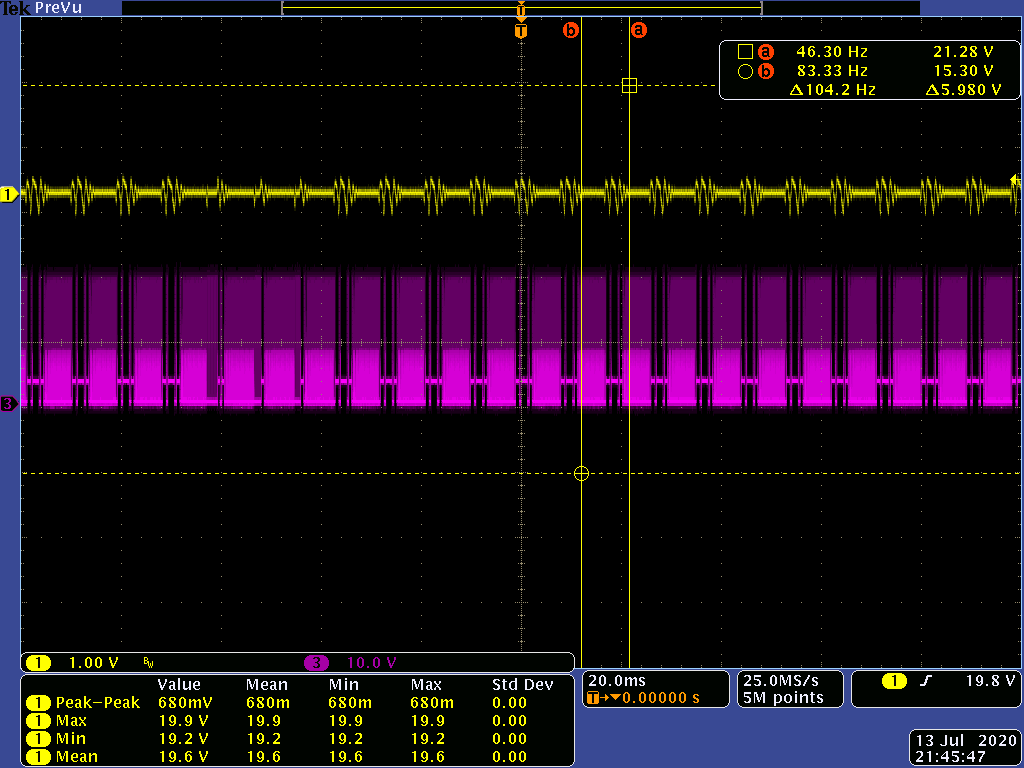
20mA load
Could you let me know why?
Regards,
Roy