This thread has been locked.

If you have a related question, please click the "Ask a related question" button in the top right corner. The newly created question will be automatically linked to this question.

TPS65910: VRTC startup issue

Part Number: TPS65910
Other Parts Discussed in Thread: AM3354,

Hi,

We have multiple production runs with TPS65910A31A1 that do not start.  The VRTC level only reaches ~1.1V instead of 1.8V, and VREF stays near zero.  The processor powered is the AM3354BZCZ.

Per SWCU093F the A31A1 VRTC does not go into low power mode in OFF state, but from reading other posts I gather that at power-up it only supports 100uA.  Our product uses VDAC to power AM3354 VDDS_RTC (uses GPS for time) and therefore the load on VRTC (sans the 65910 BOOT1 pin) is about 19uA.

We have verified that reducing the VRTC output capacitor to 100nF has a positive effect, but is neither the root solution nor within TI spec.  I would rather ensure that loading does not exceed 50uA.

I gather that BOOT1 is a possible > 100uA current sink at power-up.  We currently have that connected direct to VRTC.  Can you please confirm that BOOT1 requires a series resistor before we spin the board?

Thank you,

Mark Latham

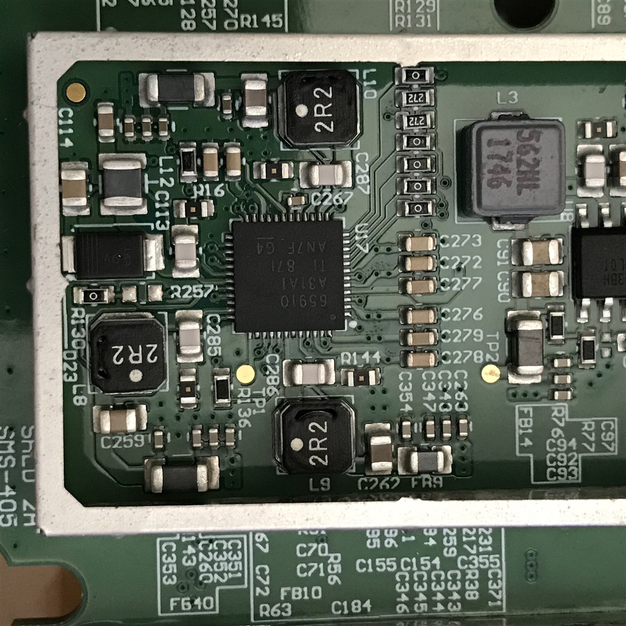
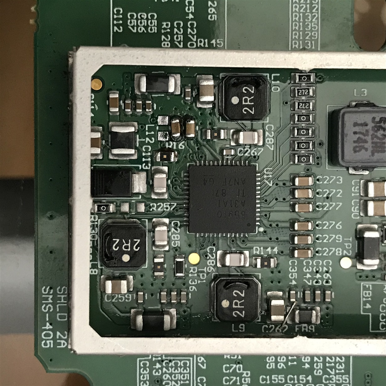
  • Please provide a photograph showing the top-side marking for one or more of these TPS65910A31A1 devices.

  • Hi Brian,

    Please see attached.  The second image #4943 is one with the issue we are seeing.

    Thank you,

    Mark Latham

  • Hi, Mark,

      There are 2 issues with the second image #4943:

    1. R16 (I guess) is missed.
    2. C354 and C262 may be shorted. 

       I'll let Brain to give his comments. 

  • Hi Phil,

    Stray wire - the contact points are all the same node (see below), so no harm and unrelated to VRTC startup.

    R128  - removed because it caused at 180uA drain on VRTC (assuming the 65910 GPIO was at 0V).

    Of course this is just one board, from one production run, and we've had many with VRTC issues.

    Thanks for your response, very astute!

    Mark Latham


  • Mark,

    Something does not add up here. If you refer to TPS65910 datasheet, it clearly says:

    VRTC Rated output current, IOUTmax:

    • On mode = 20 mA (full-power mode) 
    • Back-up mode = 0.1 mA (low-power mode) 

    Depending on which device you order for DDR3 applications, VRTC is either in low-power mode or full-power mode at startup:

    • TPS65910A3A1 = VRTC in low-power mode at startup
    • TPS65910A31A1 = VRTC in full-power mode at startup
      • Confirmed - Top-side marking on your device is "65910, A31A1"

    BOOTx pins do not consume significant power and the RTC LDO is capable of delivering up to 20mA. 180uA should not be enough to cause RTC LDO to collapse when using the "A31" variant.

    Therefore, something else in the system is preventing VRTC from reaching 1.8V as expected. Unless you are willing to investigate the possible PCB assembly issues in more detail, we have very little information available to determine root cause.

    At the present moment, my concern is that I can identify pin 29 in your photograph and I can see it goes straight to a via but there is no visible output capacitor. It is not possible to see where this trace goes or how many other places it connects to on the board. 

  • Hi Brian,

    I can provide schematics, but would prefer to do that offline.  All TI specs. have been met, and other than the BOOT1 pin, there is only one VRTC that should be be < 1uA at startup, and 19uA coming out of reset.

    Richard Solarski recommends pull-ups (resistors) to limit the current to BOOT1 in the thread below.  In a second linked thread he recommends that the load on the VRTC LDO is less than 100uA before VCC7 has surpassed ~2.8V.

    I'm wondering whether those constraints apply to A31A1, assuming of course the EEPROM must be read before switching to 20mA.  Thus my original request for you to advise on whether we should spin the board to add a series resistor to BOOT1 in order to solve this issue.

    Thank you,

    Mark Latham

  • Hi, Mark,

      I've sent you a friend request so you can share the schematics with us for further support. 

  • Mark,

    Solution: leave GPIO_CKSYNC floating, which matches TPS65910Ax User's Guide for AM335x Processors and TPS65910x Schematic Checklist documents.

    Any resistor connected to this pin should be marked as DNP and not assembled on the board.

  • Hi Brian,

    Thanks for reviewing our schematics.  Much appreciated!

    Best regards,

    Mark