This thread has been locked.

If you have a related question, please click the "Ask a related question" button in the top right corner. The newly created question will be automatically linked to this question.

BQ76930: BQ76930 16 cells with 2 BQ76930 schematic query

Part Number: BQ76930

Hi

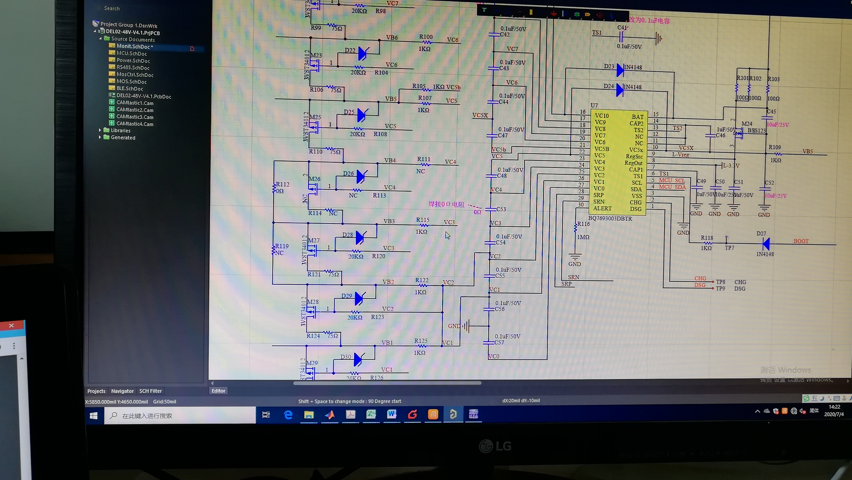
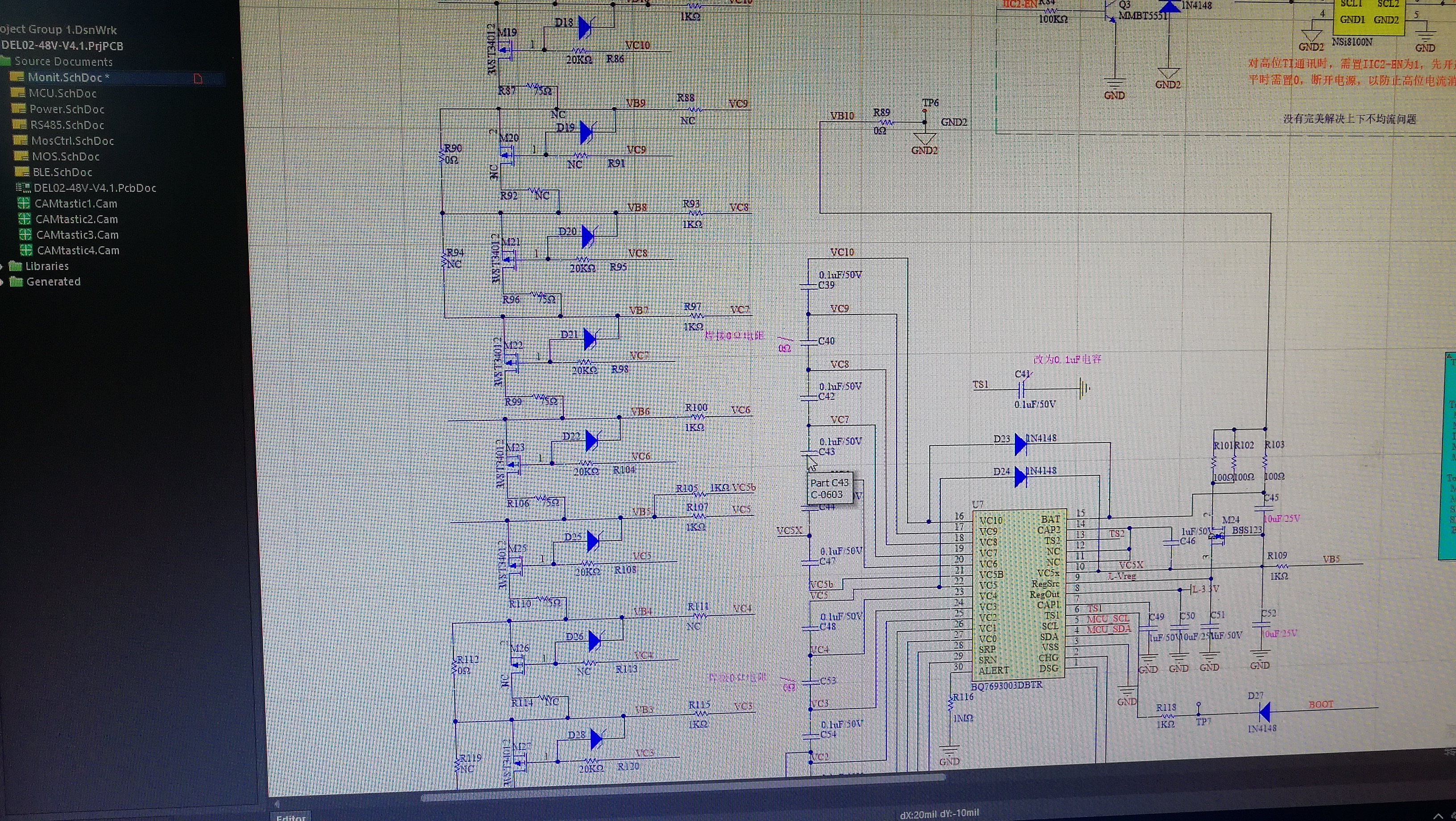
My customer design 16cells with 2 pieces of BQ76930, every pieces control 8cells.

The 4th cell is connect with 1kohm resister the voltage will fluctuate by 200mV. If the sampling resistance on the board is changed to 2K, there will be no fluctuations.

Why change the resister the voltage is stable?

Thanks

Star

  • HI Star,

    I don't see an issue with the schematic that would cause cell 4 to vary.  A common experience if Schottky diodes are used at D23 and D24 is that the thermistor bias will load the BAT and VC5X voltage during temperature samples by about 300 mV (when hot) and may pull down the VC5 voltage some.  The schematic here shows a standard diode.  Replacing R107 with 2k should make a voltage change from the diode current larger. 

    When the TS2 temperature is sampled current will flow into from BAT out TS2 through the thermistor and return to VC5X. R103 is 100 ohm which will drop less voltage from the thermistor bias current, it will also allow more current drain during short circuit, see http://www.ti.com/lit/slua749 section 3.  1k is commonly recommended for Rf.

    If the variation is on a 2 second interval it is likely the temperature sample.  Inspect the TS pins, VC5X, and the input voltage with a scope to check for alignment.  Of course be sure the register setup is the same between the tests, if the TEMP_SEL is not set to external the thermistor will not be sampled. 

  • He did not describe my problem clearly.
    Let me describe the problem again.
    I used BQ76930 to make a BMS board with a filter resistance of 1K. When controlling 20 series of batteries, a 1K resistor in series between the battery pack and the sampling harness of the BMS board will not affect the sampling accuracy. When controlling 16 series of batteries, the upper and lower plates control 8 series each, and a 1K resistor is connected in series between the battery pack and the 4 cell sampling harness of the BMS board. The sampling voltage will fluctuate by 200mV, If the sampling resistance of the 4 cell on the BMS board is changed to 2K, there will be no fluctuations. Equalization is not turned on in all tests. What is the reason?
    When controlling 8 series, VC3 and VC4 are short-circuited, and VC8 and VC9 are short-circuited. If a 1K resistor is connected in series with the 3 cell sampling harness, the sampling accuracy of the 3 cell will not be affected, that is, a 1K resistor connected in series at the short-circuit will not affect sampling. Accuracy, the resistance of the adjacent series in the short circuit will affect the sampling accuracy.

  • Hi Nan,

    At the boundary cell connection between the cell groups of BQ76930 there are several currents which could affect the node voltage if there is impedance to the cell:

    • Sampling current for the upper group (VC5B), dICELL in the data sheet.
    • Sampling current for the lower group (VC5), note the pin input current is higher than others dICELL
    • Supply current (VC5X), dINOM
    • At VC5X also, dIALERT if ALERT is set
    • Thermistor load current for above or below group.  At room temp either can be about 165 uA, with the thermistor shorted about 330 uA, when hot perhaps 250 uA.  At boot these will roughly align, with time they will drift an can be observed as distinct pull up and pull down of VC5X (for example)
    • Cell balance/equilization current influence if running, in your case it is not

    A common resistance between the cells and the BMS board node will cause a voltage shift from any current change, the part should be able to measure that.  With 10 cells cells 5 & 6 are at the boundary and could be affected by this variation.  With 8 cells cells 4 & 5 will be the cells connected at the group boundary and would be affected by the current.  The connection of VC4 and VC3 together will have the dICELL of both inputs added, the shorted cell4 of the part is still measured in the device, it has no physical cell in the 8 cell battery.

    I don't see a reason you would have a 200 mV variation with a 1k resistance and no variation with 2k, or that it would show up on cell 4 of an 8 cell battery but not cell 5 of a 10 cell battery unless there is a setup variation for the 2 tests.  200 mV should show up on an approximately 14V battery, you might confirm it is observable with an oscilloscope.  With more resistance the variation should be larger.  A technique to avoid possible setup changes may be to use 2 parallel 2k resistors to make the 1k resistance, then disconnect 1 during operation to change to 2k without resetting the electronics or parts configuration. 

  • Thank you for your answer. The way I collect voltage is to read the register directly and read it once every 250ms. If there is fluctuation, it will appear several times in a row, then it will be normal, and then it will appear continuously. The fluctuation may be upward or downward.

    As you said, if the current change at any place will cause the sampling voltage to change, why does the sampling voltage not fluctuate when controlling 10 series of batteries and connecting 1 ~ 20K resistor to the sampling harness of battery pack and BMS board.

    When controlling the 8-cells batteries, this fluctuation is not only found in the 4 cells, but also in other series connected resistors except for the 3 and 7 cells. I also tried to remove the equalization circuit, leaving only the sampling circuit, which is the same situation.

    After removing the equalization circuit, short circuit the 4 cell 1K resistor on the BMS board, and connect 1K resistor to the sampling harness of battery pack and BMS board. The sampling voltage will also fluctuate.

    I also contacted our supplier, who used your circuit board to do this test and also reproduced the fault.

  • Hi Nan,

    Increasing the input resistance for the cell inputs is not recommended operation, but it can be an interesting technique to observe sampling currents. I do not know a reason the variation would go away over time.  The timing of the 2 cell groups does drift with respect to the other.  A 200 mV variation on 1k would indicate a 200 uA current.  Again it is consistent with a possible thermistor sample, but the thermistor timing is every 2 seconds, not continuous samples.