This thread has been locked.

If you have a related question, please click the "Ask a related question" button in the top right corner. The newly created question will be automatically linked to this question.

TPS1H100-Q1: some questions about TPS1H100A drive PTC heater

Part Number: TPS1H100-Q1

Hi,

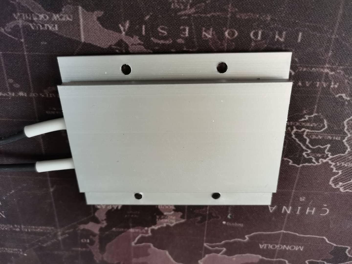
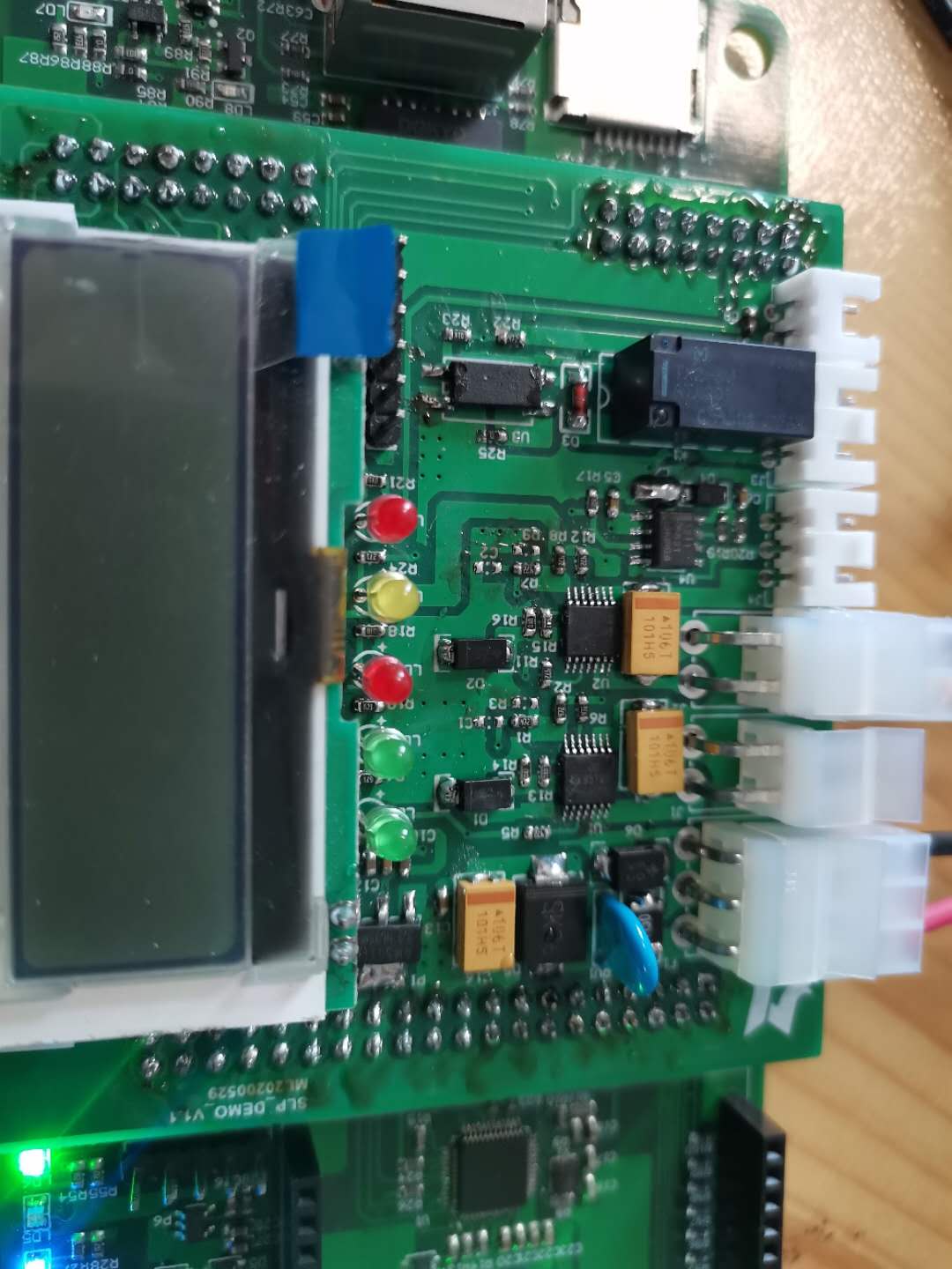
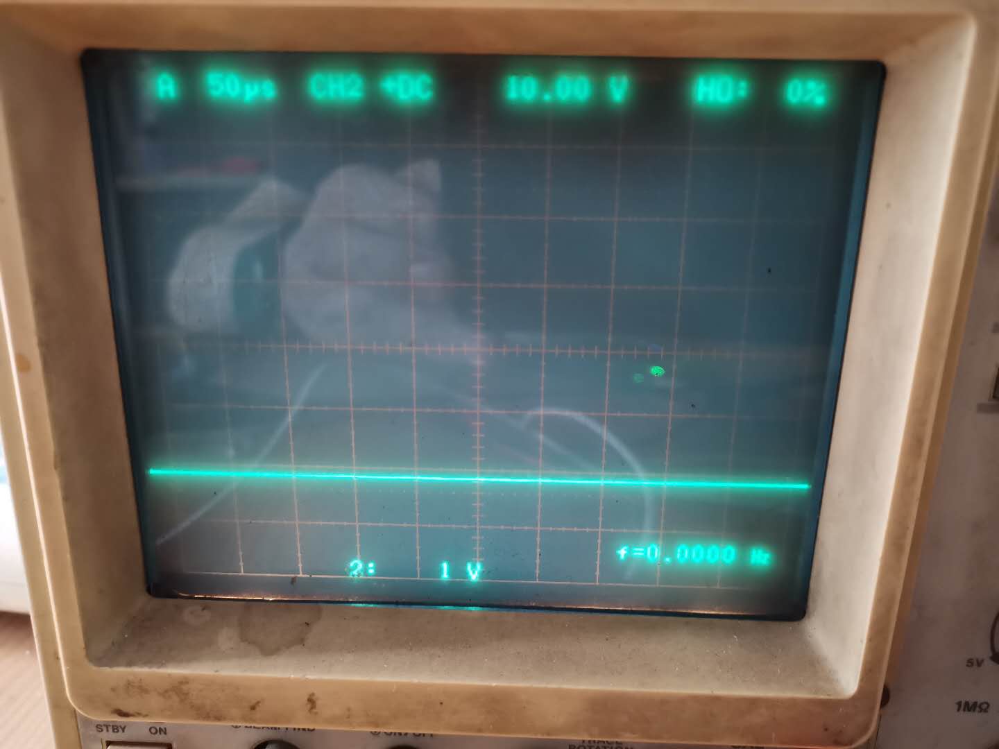
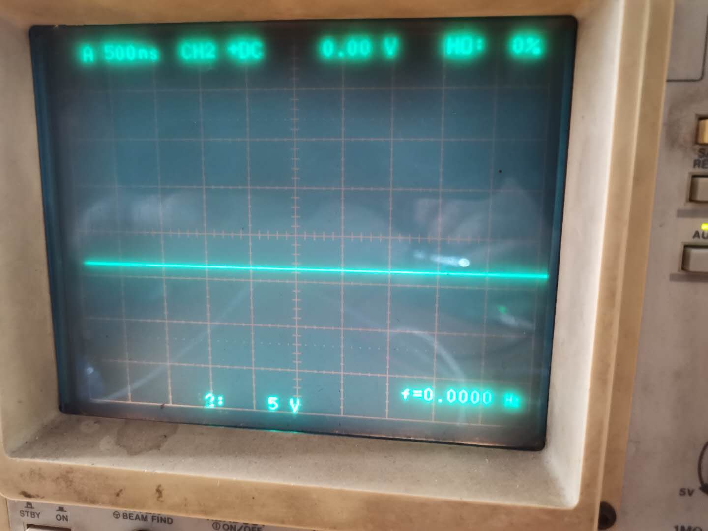
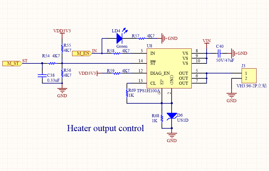
    I use TPS1H100A to drive PTC Heatheater.pdfer(Similar to PTC resistance).power input is +24VDC, In the initial state, the PTC is 10 Ohm,when PTC loaded, the output of TPS1H100A drop to 1.4V and the chip is very hot.

  • Hi,

    Would you be able to share voltage waveforms at the output, input, and /ST pins when this occurs? Also would be helpful is to see the current at the output. Are there any capacitors that are attached to the output?

  • Hi Anthony :

           I've solved my problem,I changed R15 to 500 Ohm and PTC can be drived.

    But I have one more question:the PTC is a variable current and resistance load, when it was powered on, the PTC as 1.71A@6 Ohm, the TPS1H100A output is 0.8V, so ST pin is 0. When the temperature rises steadily, the PTC as 0.7A@ 34 Ohm, the TPS1H100A output is 24V, so ST pin is 1.How can I improve that the chip doesn't alarm?

    Regards,

    Ivan Cheung

  • Hi Ivan,

    Is it possible that you can provide some waveforms? Are you referring to the temperature of the PTC or the device? If you are able to provide some waveforms, this will reduce the possibilities on why the ST pin is pulled  low before being pulled high (represents normal operation). 

    A few reasons why the /ST pin could be pulled low are: 

    • Short to GND
    • Open Load
    • Short to Battery
    • Reverse Polarity
    • Thermal Shutdown
    • Thermal Swing

    As the PTC seems to be operational, it does not sound like the device is having issues now that you've increased your current limit to 4.932A using the 500 Ohm on the CL pin

    Would you be able to provide more information such as waveforms showing voltages and currents where the device turns on and the device shows /ST pulled low?

  • Hi Anthony !

          1). PTC is my load and I use it to heating board. It is a constant power element about 13.5W . Its internal resistance is 6 ohm at room temperature(25℃) and 34 ohm at 80 ℃.

          2). In my SCH, the VIN=24VDC, I use STM32F207 to control pin "IN". I think when "IN=1", the pin "OUT" of TPS1H100A can drive the PTC, but at this time,  I measured pin "OUT" only 0.6V and pin "ST" is 0.5V.

               I think the chip is protected.

          3). How can I use TPS1h100A to drive a load with low impedance and variable current?

  • Hi Ivan,

     PTC is my load and I use it to heating board. It is a constant power element about 13.5W . Its internal resistance is 6 ohm at room temperature(25℃) and 34 ohm at 80 ℃.


    With a 24V supply, this results in an estimated constant current of 5.5A. With 6 ohm at room temperature, based on the 24V supply, this is 4A. At 34-Ohms, this is about 0.7A. Please be aware that the device is rated to 0 to 4A for a DC continous load current.

    In my SCH, the VIN=24VDC, I use STM32F207 to control pin "IN". I think when "IN=1", the pin "OUT" of TPS1H100A can drive the PTC, but at this time,  I measured pin "OUT" only 0.6V and pin "ST" is 0.5V. I think the chip is protected.

    Based on the information you've given me:

    • Device shows /ST pin low when IN is pulled high
    • Output load is low impedance initially and output voltage is low
    • After increasing temperature of the PTC(?), the device shows proper output voltage

    This may be due to an initial inrush current at startup. From what you've given me, I am unable to see if there are any capacitors on the output or capacitve elements from the PTC that may be causing this inrush current and limiting the current due to the inrush current. This current may also just be due to the low impedance at startup.

    This inrush current can cause the device to heat up initially and results in a thermal shutdown, which causes the device to reduce the output current half the current limit. 

    This thermal shutdown is the protection by the chip if it is heating up.

    There are things I'd like to confirm since you have not given a waveform with this information, again, waveforms would be more telling of the situation and I"d be able to diagnose the situation more accurately. 

    How can I use TPS1h100A to drive a load with low impedance and variable current?

    As long as the device is not heating up to the thermal shutdown threshold, the device should be used according to the datasheet. 

  • Hi Anthony,


    This is my load PTC. It is a variable resistor at 6Ohm@25℃ and 34Ohm@80℃.


    This is my board and I ues two pcs TPS1H100A, one is to drive motor and RCL=1K, the motor is OK. The other is to drive PTC and RCL=510Ohm, the PTC doesnot work well.

    I use a 24VDC@300W switching power supply to power my board.


    This is GND waveform.


    This is out wavefrom. When it starts,no load condition, I set IN=1, VS=24V. When the load is applied,you can see Vout=6.4V(Iout=1.7A), ST=0 and VS=6.4V, the PTC does not work well. 

    After about 20 minutes, when the temperature of PTC rises, the resistance of PTC increases,  the Vout will rise to 24V(Iout=0.6A) , VS also rise to 24V and ST=1.

    What should I do with this st = 0 process? I donot need this process .

    best regards

    Ivan

  • Hi Ivan,

    Awesome, appreciate the waveforms. Do you have a schematic you can share?

    And just to clarify

    • After 20 minutes, the ST goes from 0 to 1?
    • Is there a part number for the PTC?
    • What are you using to supply current? Is it a battery or a supply? If it is a supply, is there a current limit set?
    • What is the expected current draw of the PTC?

    After about 20 minutes, when the temperature of PTC rises, the resistance of PTC increases,  the Vout will rise to 24V(Iout=0.6A) , VS also rise to 24V and ST=1.


    This leads me to believe it may be a current limit issue where the current is too high initially, limited, and then causing a thermal shutdown until the reduced current load.

    What should I do with this st = 0 process? I do not need this process. 

    A few reasons why the /ST pin could be pulled low are: 

    • Short to GND
    • Open Load
    • Short to Battery
    • Reverse Polarity
    • Thermal Shutdown
    • Thermal Swing

    These are to indicate that there is a fault occuring in the system which is also shown by the VS supply being pulled low.

  • Hi Anthony ,


    This is my SCH and R56,C38 is NC.

    After 20 minutes, the ST goes from 0 to 1?---------------YES

    Is there a part number for the PTC?------------------------NO, It is a variable resistor and current at 6Ohm,1.7A@25℃ and 34Ohm,0.75A@80

    What are you using to supply current? Is it a battery or a supply? If it is a supply, is there a current limit set?--------------------a DC powersupply  24V@12A no current limit set

    What is the expected current draw of the PTC?-----at start is 1.7A and when the temperature of PTC rises to 80℃, current is 0.75A

  • Hi Ivan,

    Thanks for answering the questions

    Do you have a complete schematic of the board or can you answer if there are capacitors connected to J3 anywhere else on the board?  If there is a concern for confidential information, we can continue this thread over email (a-pham@ti.com). 

    A 1k resistor correlates to a 2.466 A current limit. How are you measuring current? You mention that the PTC is 10 Ohm at startup at the beginning of your post, what is the current at startup? Is the device still hot now that you've changed the resistor?