This thread has been locked.

If you have a related question, please click the "Ask a related question" button in the top right corner. The newly created question will be automatically linked to this question.

UC3875: Startup issue

Part Number: UC3875

Hello TI!

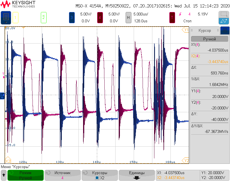
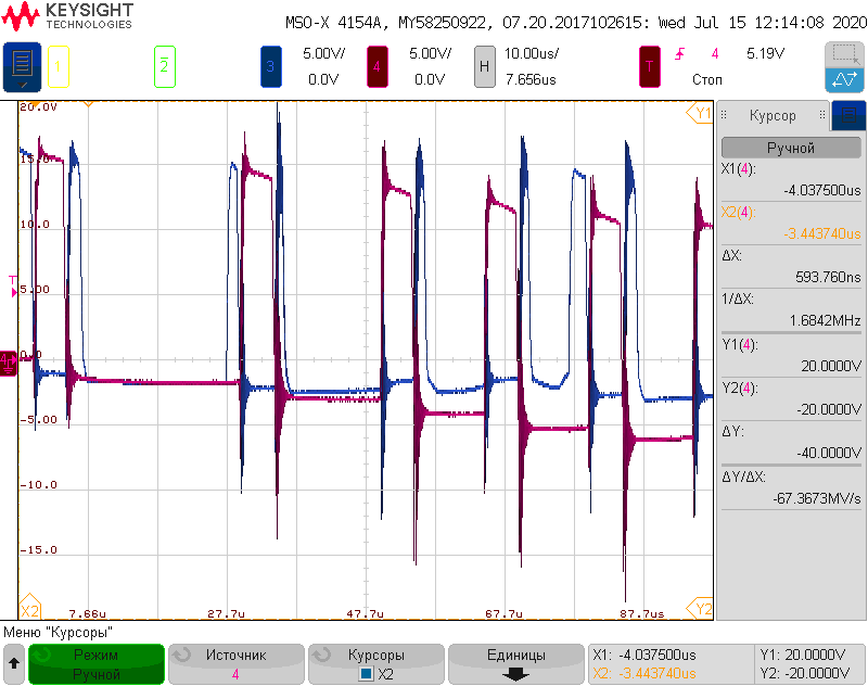
I got another issue with UC3875. Now it's turn-on problem. When the 18VDC (300 mA limited) is applied to the PWM controller, it starts up, but the PWM signal is unstable: there are gaps in cycles, and the duty cycle is not always 50% as it should be. Later (5-15 mS), the situation returns to normal and the PWM works fine. The situation gets worse when I apply the main voltage (200VDC) and then turn on PWM controller. Once, with such a turn on, transistors A and B burned out. If I first turn on the PWM controller and only then apply the main voltage, everything is ok. What could be the reason for this behavior? SS is working fine by the way. Please note, there is no feedback loop now, for test purpose and CS pin is tied to SGND also.

waveforms on QA (GS) and QB (GS)

regards,

Vasily.

  • Hello Vasily,

    One possibility could be that there is noise induced into the controller through the gate drivers. you can try to add schottky diodes to GND and to Vcc.

    The gate drive signal waveforms that you attached look very distorted, where have you connected the GND of the scope for these signals?

    Regards,

    Sonal

  • Hello, Sonal!

    I already modified PCB and add 4 fast diodes (please, see schematic below). The signal is indeed distorted, I measured it directly on Gate and Source of transistors leads, using differential probes. The one thing to mention, is that as I increase main voltage (150VDC->250VDC) the amount of noise is dropping significantly and at 300VDC gate signals looks much cleaner.

    Regards,

    Vasiliy

  • Sonal, hello again!

    Last three days I tried to make UC3785 work with other gate driving transformer. And there was 2 main problem 1- unstable work (suddenly turning off and on) and high current consumption around 300mA which make SOIC package quite hot. And this is what I was thinking: my transistors are quite beefy, 47N60C3 (Qg=320nC Ciss=6800pF). Couldn't the driver simply not be able to handle such a load? And this leads to such failure. To be honest, I did not find a parameter in the datasheet to match it with my transistors. Yes, I know that the impulse current up to 2A and 0.5 DC, but how to assess if this is enough for my transistors. Could you please tell me?

    Regards, Vasiliy.

  • Hello Vasiliy,

    Apologise for the late response.

    It could be a possibility, but I cannot say anything for certain unless I see a waveform. May you please share the Vcc and Iin. If the controller is getting too hot it could trigger the thermal shutdown of the controller which could be the reason for the controller shutting down. Can you take a scope shot of the shutdown event looking at the Vcc current, Vcc voltage, gate drive waveforms?

    Regards,

    Sonal

  • Hello Solan!

    When I said that controller gets hot, I mean only 50-60 deg.C (measured with thermocouple direct on IC) which is fairly lower that specified near 100 deg.C absolute maximum. What is thermal threshold level for UC3875 buy the way?

    Recently I tried to implement other transformer configuration to somehow solve this problem. Please, see my new configuration below.

    It seems, double-ended transformer configuration improved situation - there was no gaps at start-up, but turn-on/turn-off rise and fall time were rather bad (from 500ns up to 2us depending on transformers cores and windings) and the decreasing of gate resistor (even down to 1R or short) did not done much. My goal was to achieve <=200 ns for gate voltage rise up time, and I started decreasing transformers windings. I began from 30 turns at primary with Lm=2 mH and was decreasing primary and secondary windings. Configuration, that gave me near 250 ns of rise time has only 15 turns for primary winding and 7 turns per secondary windings. I know, that is recommendation for Lm to be near 2mH @ 100 kHz, but such configuration does not make its job done in terms of rise/fall time, so only way I see now is to significantly drop this inductance. (I don’t know why high value of Lm is limiting factor for rise time. Parasitic L and C maybe?...)

    My current gate transformer have follow characteristics:

    1:0.5:0.5 (15:7:7)

    Wire cross section: 0,16mm2

    Core: EFD 20 (Ae=31mm^2)

    Core material: N87 (Al=1200 nH/N^2)

    Lm = 460 uH

    V driver = 18VDC max

    Bmax=Vmax*dt/N*Ae=(18*5*10^-6)/(15*31*10^-6)=0.19T which is should be far from saturation.

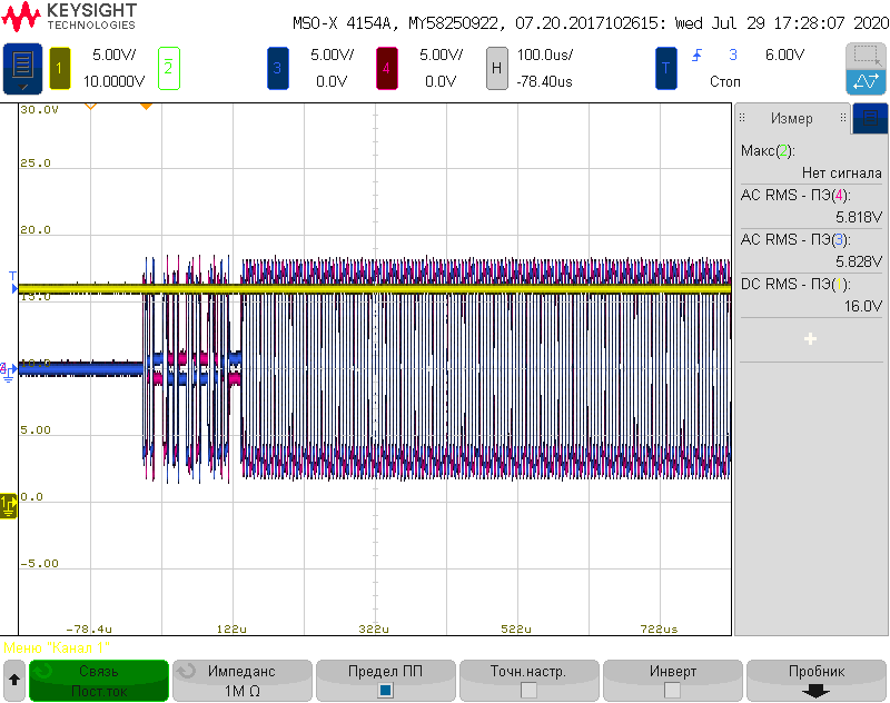
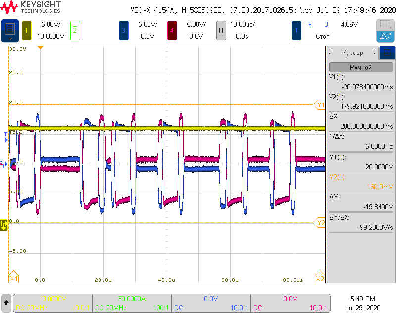
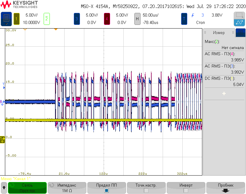
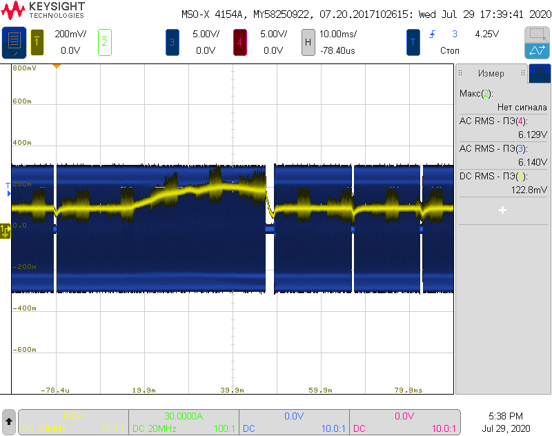
    Let's get to the point: with this configuration all works just fine with only one transformer connected to IC at the time: TAB or TCD only. As soon as I connect both of them TAB and TCD to the IC it's total RMS current consumption is 150-200mA@16 VDC and problems returns. There is again unstable PWM generation with gaps in pulse sequence. I measured all voltages in failure condition as you recommended, but there was nothing suspicious about them at all. Please see waveforms below.

    Yellow is voltage on Vc pin red/blue is voltage on gates QA and QB respectively

    Yellow is voltage on Vin pin red/blue is voltage on gates QA and QB respectively (same with previous because R4 is shorted)

    Yellow is voltage on Vref pin red/blue is voltage on gates QA and QB respectively

    Yellow is voltage on 1R resistor in series with supply voltage (input current another words)  red / blue is voltage on gates QA and QB respectively

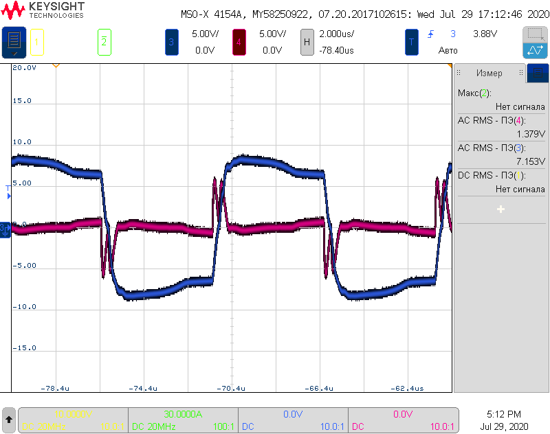
    And here is working condition (only TAB is connected) blue is waveform on QA gate-source and red one is waveform on 10R resistor in series with the winding  (current through transformer) 

    If I lower IC supply voltage under 12VDC it’s looks stable even with both TAB and TCD connected to the IC, but as soon as I heat it up a little bit with my hot air gun (not more than 50 deg. C) it fails. At 15 VDC it works stable only if I use little copper heatsink on top of the UC3875 and a second after I remove heatsink it fails. And above 16 VDC it is failing instantly no matter what I do. 18VDC did not even try. So there's definitely some thermal effect on its operating.

    And it’s looks kind of strange because total consumption is under 200 mA and “gate” resistors 10R in series with transformer winding limits 1.8 peak current @18VDC anyway which is below maximum 2A peak driver current. So none of the maximum ratings of the IC are violated.

    I started to suspect UC3875 is defective somehow, because I did not see a reason for it to fails like this. I stuck with this problem and any advice or idea will be nice.

    Regards,

    Vasiliy

  • Hello Solan. I replaced my ultra-fast diodes (D2,D3,D11,D4,D12,D7,D13,D8) with schottky diodes and all problems gone! Thak you! I thought common or fast diodes will be fine to, but no! Schottky diodes is crucial! But if it so necessary, why schottky diodes not integrated in the IC UC3875...?

    Regards,

    Vasiliy