This thread has been locked.

If you have a related question, please click the "Ask a related question" button in the top right corner. The newly created question will be automatically linked to this question.

LP8867-Q1: LEDs flash

Part Number: LP8867-Q1

Hi,

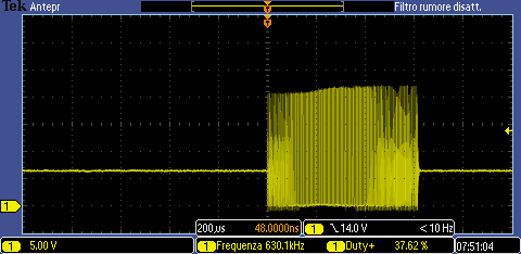
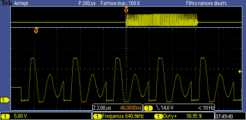
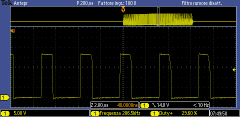
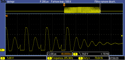
I would like to use the LP8867-Q1 LED driver to drive 4 LED strings with 120mA per channel. The output voltage for the led bar is 21V and the minimum input voltage is 5V. I tried this configuration but the LEDs flash, probably the fet exceeds the maximum allowed current of 3.5A. I can't find a spreadsheet where to calculate the boost stage. The inductor is 22uH and the frequency is 300kHz.

If I decrease the current of the LEDs it works.

If this driver does not go well, is there another led driver suitable for my requirements?

A greeting

  • Hi Davide,

    The peak current in stable status is around 2.9A. Can you measure the waveform of SW to identify the root cause?

    Will you use the external FET? Like LP8866.

  • Hi,

    as required I attach waveform.

  • Hi,

    this is the electronic scheme:

  • Hi Davide,

    What's the status of fault pin when LED flashes? Can you measure the current of inductor or output current?

    If internal current limit is triggered, the current limit would be 3.35 A for 1.6 seconds followed by 3.7-A limit for 1.6 seconds, and this 3.2-second period repeats. And you will see the LED flickers.

    In your waveforms, I can't judge the relationship between output current and SW since there is only waveforms of SW. Can you provide the waveform of output current(or the voltage of outx), and fault, the voltage of SW, and PWM input together?

  • Hi Charles,

    below I report the waveforms as required:

    Ch1 = SW
    Ch2 = Vout
    Ch3 = Vin
    Ch4 = FAULT

    PWM is set to 100%

    Not having the current probe for the oscilloscope, I zoomed in on the SW signal, so through the Rsd (on) value of the FET we can trace the current indicatively.

    From the curves I note that the problem is the decay of the measured input voltage measured on the capacitor C55. I also tried to increase the value up to 470uF but I don't solve it.

  • Hi Davide,

    I think the voltage drop on the L5 and FB1 is big when the input voltage is low and output voltage is big(The input current is big at this moment). You also need to consider the voltage drops on the input wire if it is long. UVLO is triggered according to your waveforms and device need to restart in this condition. That is why the output LED flashes. Maybe you need to change the L5 and FB1.