This thread has been locked.

If you have a related question, please click the "Ask a related question" button in the top right corner. The newly created question will be automatically linked to this question.

BQ25895: Query regarding boost converter output of the BQ25895

Part Number: BQ25895

Hello,

We are planning to integrate the BQ25895 battery charging IC into one of our products. We have a few queries related to the same.

1) We would like to have an output of 5V/2.7A (13.5W) at the PMID pin (boost converter output) continuously until the battery under-voltage protection isolates the battery from the internal boost converter. The battery protection kicks in at around 3V. Is it possible to have the mentioned output using the battery and the in built boost converter of the BQ25895? or should we go for another boost converter IC?

From what we read in the datasheet of the BQ25895, the internal boost converter will be able to provide a the load with upto 3A at 5V. The output might be limited when the battery is below 3.7V and thus for the same desired output, the current from the battery will need to be more then 4.5A (max discharge current of our selected battery) and in this case, we might not have the desired output power. Is this understanding correct?

We are including an image describing the planned connections and battery parameters.

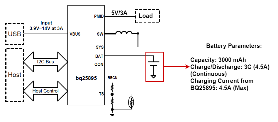
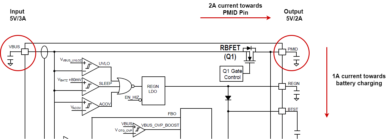
2) We also plan to have a system which can deliver power to the PMID pin as well as charging the battery in the simultaneous presence of load (on PMID) and 5V at VBUS pin. We will limit the charging current of the battery in this case. For example, if we have 5V/3A supply at VBUS pin, we can let the battery charge at 2A and the remaining power can be delivered to the PMID pin since the "RBFET" will already be on while charging the battery and power on VBUS will also be available on the PMID pin. Is this understanding correct? Please confirm. Also attaching an image of the planned solution. 

If this is not feasible, how can we achieve the above use case using the BQ25895. Kindly let us know.

Kindly respond to the above queries. Should you require any information from our side, do let us know.

Regards,

Sarth Dave

  • Sarth,

    1. It should work. The battery needs to be able to supply >13.5W power in order to maintain 5V/2.7A boost output. Please note that there’s no effective current limit for PMID by the charger. The system design should make sure PMID will not be overloaded.

    2. The device senses the input current via RBFET. If Q1 is bypassed, the charger input current limit may not be effective.

    It is highly recommended to get familiar with the BQ25895 operations by testing the BQ25895 EVM (https://www.ti.com/tool/BQ25895EVM-664) before making customized designs.

    Please visit https://e2e.ti.com/support/power-management/f/196/t/874557 for BQ2589X: Schematic Review and PCB Layout Design Tips and https://e2e.ti.com/support/power-management/f/196/t/875386 for BQ2589x/BQ25898x FAQs.

    Thanks,

    Ning. 

  • Hello Ning,

    Thanks for the response. For my second point, I will explain my use case to you again so that you can have a deeper understanding. 

    Lets say I have an input source rated at 5V/3A supplied to the BQ25895 via the VBUS pin. Once the source is identified by the IC as a DCP capable of providing 3A@5V, I will read the identified source using a micro controller and and I2C communication. Now my micro controller knows that the charger IC has an input capable of supplying 5V/3A.

    The next thing that I do is set the battery charging current limit to lets say 1A and start the charging process. So now, the internal buck converter will draw around 5W of power (5V, <1A) from the source in order to charge the battery. This current will flow from the Q1 FET and eventually through the HSFET and LSFET. So, the battery is now charging.

    In this case, Since I see in the block diagram, that the PMID pin is directly connected to the drain of the Q1 FET, and the Q1 being already on, 5V available from the source will be visible on the PMID pin. Is my understanding correct?

    If so, can I draw the remaining power available from the source, i.e 5V@2A, to power a load connected to the PMID pin?

    I hope I have made my use case clear to you. Kindly respond to this and also let me know should you have some queries.

    Again, thanks for all your efforts.

    Sarth

  • Sarth,

    The device implements Dynamic Power Management (8.2.6.2):

    When input source is over-loaded, either the current exceeds the input current limit (IINLIM or IDPM_LIM) or the voltage falls below the input voltage limit (VINDPM). The device then reduces the charge current until the input current falls below the input current limit and the input voltage rises above the input voltage limit.

    When the charge current is reduced to zero, but the input source is still overloaded, the system voltage starts to drop. Once the system voltage falls below the battery voltage, the device automatically enters the Supplement Mode where the BATFET turns on and battery starts discharging so that the system is supported from both the input source and battery.

    The device senses the input current via RBFET. It can't tell if the input current is drawn by SYS load or by PMID load. As long as DPM is triggered, it will reduce the charge current or even the battery may discharge. Please check if this is acceptable or not.

    It is highly recommended to get familiar with the BQ25895 operations by testing the BQ25895 EVM before making customized designs.

    Thanks,

    Ning

  • Hello Carol/Ning,

    I understand the points that you put. We are going to evaluate the same with the EVM as well.

    What we are attempting to do over here is the "Priority charging". Basically, when the load is present on the PMID pin and the VBUS is also present , can the BQ25895 charge the battery and deliver power to the load at the PMID pin? In our use case, the load the PMID pin will be a priority. If the adapter voltage (VBUS) is present, the power shall be supplied to the load at the PMID pin with higher priority than charging the battery.

    Is this possible directly within the IC? 

    or do we need to add some control switch (like a MOSFET) and plan some logic so that when the VBUS is present, power priority to the load can be achieved over the battery charging.

    Thanks and regards,

    Sarth

  • Sarth,

    The load at SYS pin is the highest priority for the charger. In normal charge mode, PMID is used to supply the charger operation. Please refer to 9.2 Typical Application for the details.

    Thanks,

    Ning.