This thread has been locked.

If you have a related question, please click the "Ask a related question" button in the top right corner. The newly created question will be automatically linked to this question.

LM5022: Sepic converter build based on PMP7305 does not work

Part Number: LM5022

Hello Engineers,

I have built sepic converter based on www.ti.com/.../PMP7305

Unfortunately Q2 burned up few seconds after power up. Before that I was able to measure output voltage - it was something about 60V without any load.

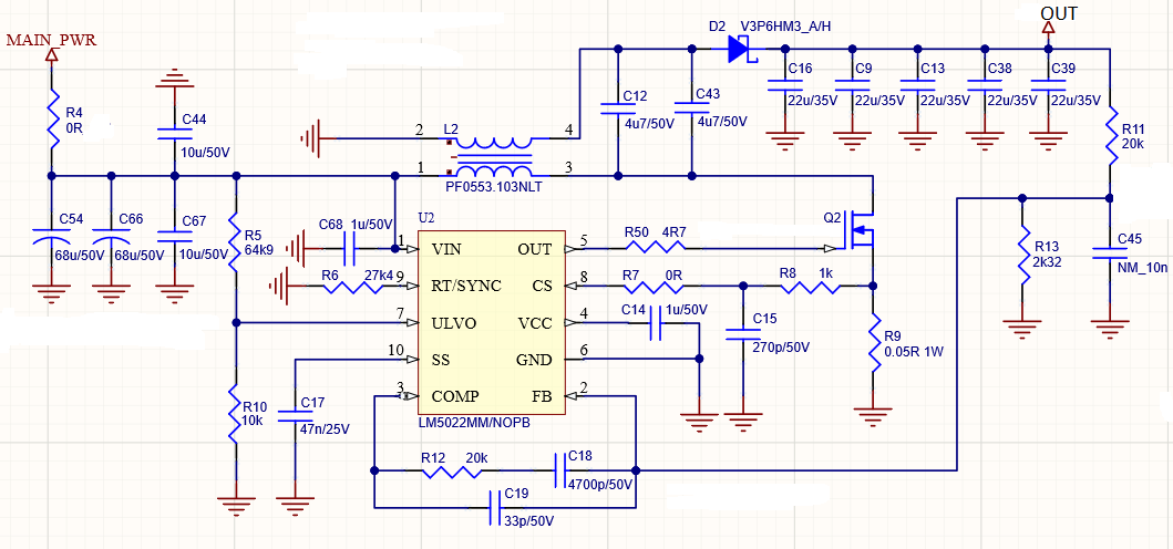
This is how my design looks like:

Designator Name Footprint Part number
C54, C66 68u/50V HA0 HHXC500ARA680MHA0G
C9, C13, C16, C38, C39 22u/35V C1210 GMK325BJ226MM-P
C14, C68 1u/50V C0805 UMK212B7105KG-T
C12, C43 4u7/50V C1206 UMK316AB7475KL-T
C15 270p/50V C0603 CC0603KRX7R9BB271
C17 47n/25V C0603 CC0603KRX7R8BB473
C18 4700p/50V C0603 C0603C472K5RACTU
C19 33p/50V C0603 C0603C330K5RACTU
C44, C67 10u/50V C1210 UMK325AB7106KM-T
D2 V3P6HM3_A/H SMP_DO220AA V3P6HM3_A/H
L2 PF0553.103NLT PF0553.103NLT PF0553.103NLT
Q2 BSC065N06LS5ATMA1 TDSON-8 BSC065N06LS5ATMA1
R5 64k9 R0603 CR0603-FX-6492ELF
R6 27k4 R0603 CR0603-FX-2742ELF
R7 0R R0603 CR0603-J/-000ELF
R8 1k R0603 CR0603-FX-1001ELF
R9 0.05R 1W R1206 WSLP1206R0500FEA
R10 10k R0603 CR0603-FX-1002ELF
R11, R12 20k R0603 CR0603-FX-2002ELF
R13 2k32 R0603 RC0603FR-072K32L
R50 4R7 R0603 RK73H1JTTD4R70F
U2 LM5022 VSSOP-10 LM5022QDGSRQ1

I'm going to replace Q2 but before that I have few questions:

1. Do you see any errors in above schematic and/or PCB?

2. Are there any steps that should I do when I will run it again to prevent burning up again?

  •  R11/R13Hello Tadeusz,

    seems the loop is not closed, so the system is not going into regulation.
    Via softstart duty cycle increases to maximum, output voltage goes to maximum.
    Stress at FET and rectifier becomes Vin + Vout, FET blows up around Vds 66V to 72V.
    Fits to your description above.

    Check your feedback divider R11/R13 and check compensation R12/C18/C19;
    please check values AND connection. At feedback pin #2 you need to measure
    reference level 1.25V in regulation.

    This would be my very first action item, best regards, Bernd

  • Hello Bernd,

    You are right - there was no connection from divider R11/R13 to feedback pin. So short wire fixed this issue.

    Many thanks.

    Regards,

    Tadeusz

  • Hello Tadeusz,

    good to read that the board is fixed;
    please be aware that the output has seen 60V,
    so beside the broken FET a replacement of Schottky rectifier,
    flying capacitor and output capacitors might be beneficial for reliability.

    Best regards, Bernd

  • Hello Bernd,

    thanks for suggestions - I've already replace all outputs components and it works however I see much bigger voltage spikes on output that it is shown in reference design test results (page 4): www.ti.com/.../snvu121.pdf

    Do you have any idea how to fix this?

    Regards,

    Tadeusz

  • Hello Tadeusz,

    the output current at SEPIC topology is discontinuous, a pulsed current;
    so there is ripple and noise per default...

    Please check your probe setup, do not use ground wire, just use a short ground clip
    and measure across output capacitor. A long ground wire is a loop antenna,
    field lines are passing through this loop and injecting noise, radiated noise.

    And last but not least, I checked the word file of the test report, so I could magnify the
    scope screenshot - bandwidth limitation has been activated at that measurement.

    If you need to reduce the noise:
    - main topic, 100% perfect layout
      shortest loops, input/output caps back-to-back, small switch node area,
      no corners at switch node polygon (corner is a wideband antenna),
       solid ground plane
    - shielded inductor, keep core away from saturation; saturation means that field lines are
      leaving the core
    - add cap ladder at output, small caps like 10nF, 100nF offer lower impedance at RF
      place close to rectifier
    - add RC snubber in parallel to rectifier
    - gate resistor could reduce spikes sligthly
    - add ferrite bead to output (=cost) to reduce spikes and noise
    - add post filter to output to reduce ripple (=more cost) to reduce ripple
    - add post linear regulator w/ high PSRRR to output(=maximum cost)
      (output voltage of SEPIC needs to be set to Vout + max dropout of LDO)

    That's what I got in my drawer for you, best regards, Bernd