This thread has been locked.

If you have a related question, please click the "Ask a related question" button in the top right corner. The newly created question will be automatically linked to this question.

Follow up for BQ27200 and 24070 - Datasheet shows 'Li-ion Protector' as a block.

Other Parts Discussed in Thread: BQ27200

Do I read that to be a requirement of any Li-ion system?  I assume it is a separate part; maybe for watching current and turning on/off the main 'valve'? 

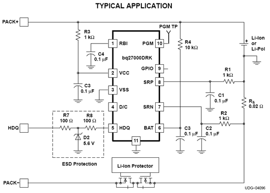
I am using both the BQ27200 (which is where I see the protector block) and the24040.  The BQ27200 datasheet makes it look like I need a Li-ion protector circuit.  Does anybody know what this is?

Thank you.

  • The "Protector Block" represents the primary protection circuitry generally built into the pack by the pack manufacturer.  The "Protector Block" controls a pair of back-to-back MOSFETs that are able to interrupt the current path through the battery.  The "Protector Block" prevents over charge, over discharge, and operation of the battery outside a temperature window.  This circuit function is usually called Primary Protection in the literature and data sheets.

    Best Regards, S. Dunbar, AFA Colorado

  • Okay, so maybe I am using the BQ27200 incorrectly?  The Sanyo battery shows the protection FETs as part of the on-battery circuit (it also has an IC that appears to be some sort of supervisor that controls the gates to the FETs).  So the terminals coming from the battery, which plug into my board, are PACK+ and PACK-; already having gone through the FETs.

    The application diagram on the BQ27200 datasheet show the sense resistor between CELL- and PACK-.  Can I implement this the right way if I'm already working downstream from the FETs?  I would think it should be okay as long as the sense resistor is between the main battery - terminal and the system - (return path - gnd).

    I know the BQ27200 is ideally supposed to be built into the battery pack, but can I use it as a fuel gauge by putting it between the battery negative terminal and the system negative terminal?

    Thanks for posting your thoughts on this S. Dunbar.

    -David

  • David-


    You can use the bq27200 outside of the pack but notice that the bq27200 is powered by the cell.  If you use the bq27200 outside of the protection circuitry, if the Protector trips and disconnects the battery (for the aforementioned variety of reasons) you may need to go through a charge/discharge cycle again the regain accuracy.  In most applications this is probably not a big deal- the temperature window is very wide (and rarely trips) and you're likely damaging the cell anyway if this trips the protector; if you overcharge or underchange the cell thereby tripping the protection again there is possible damage and a learning cycle will again be in order.

    Long story short, if your application environment is such that the temperature variation is unlikely to trip the protection and you have good control over the charge/discharging of the cell such that you're NOT relying on the Li-ion Protector, you should have no problems.  The Protector is generally the last line of defense to protect the cell from damage, which is why it is in independent IC from the rest of the system.

  • Hey thanks Antennahead!  I'll look into the specs on the temperature variation and understand that better, but the idea that the BQ27200 should be powered by the cell makes great sense.  I had not thought too deeply about the implications of the IC being powered directly by the cell. 

    I suppose then, that I will still want the IC to essentially sit between the battery (with the protection FETs) and the system, with the sense resistor between the negative terminals.  So the return current path for the IC ground will be the negative terminal of the battery and the return current path for the rest of the system will be what is shown as PACK- in the diagram.  Is that right?

    Thanks again, I appreciate the time you've spent helping me.


    -David

  • Correct.  Just put the sense resistor between Pack- and 0V (or Ground, or Return, whatever you call it) of your application circuit.


  • Also, the power supply for the bq27200 should be PACK+ so that the device core remains active at all times. 

  • Right, I got it.  Thanks!