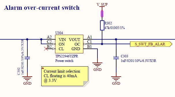
Serious problem here with TPS22946YZPR.
Randomly the chip does not start.
Happens on many device we tested.
There appears to be a relation with the time the input power was off.
We could reproduce this several times with power off between 2.5 and 4.5 seconds.
No permanent damage, the device works again after the event.
Cannot tell (yet) what happens if the ON input is cycled when the situation occurs.
The load is light.
Disconnecting load does no help
1.2 kOhms from OC to GND does not help.
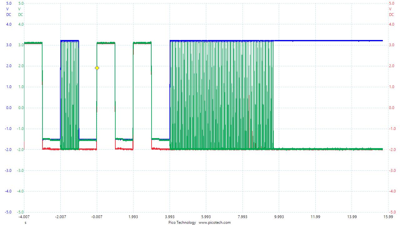
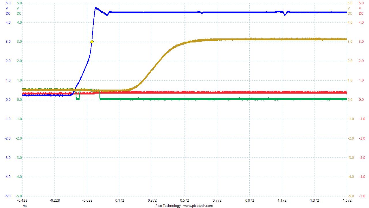
Traces:
Horizontal: 200 us/div
BLUE: Vin / ON
RED: Vout
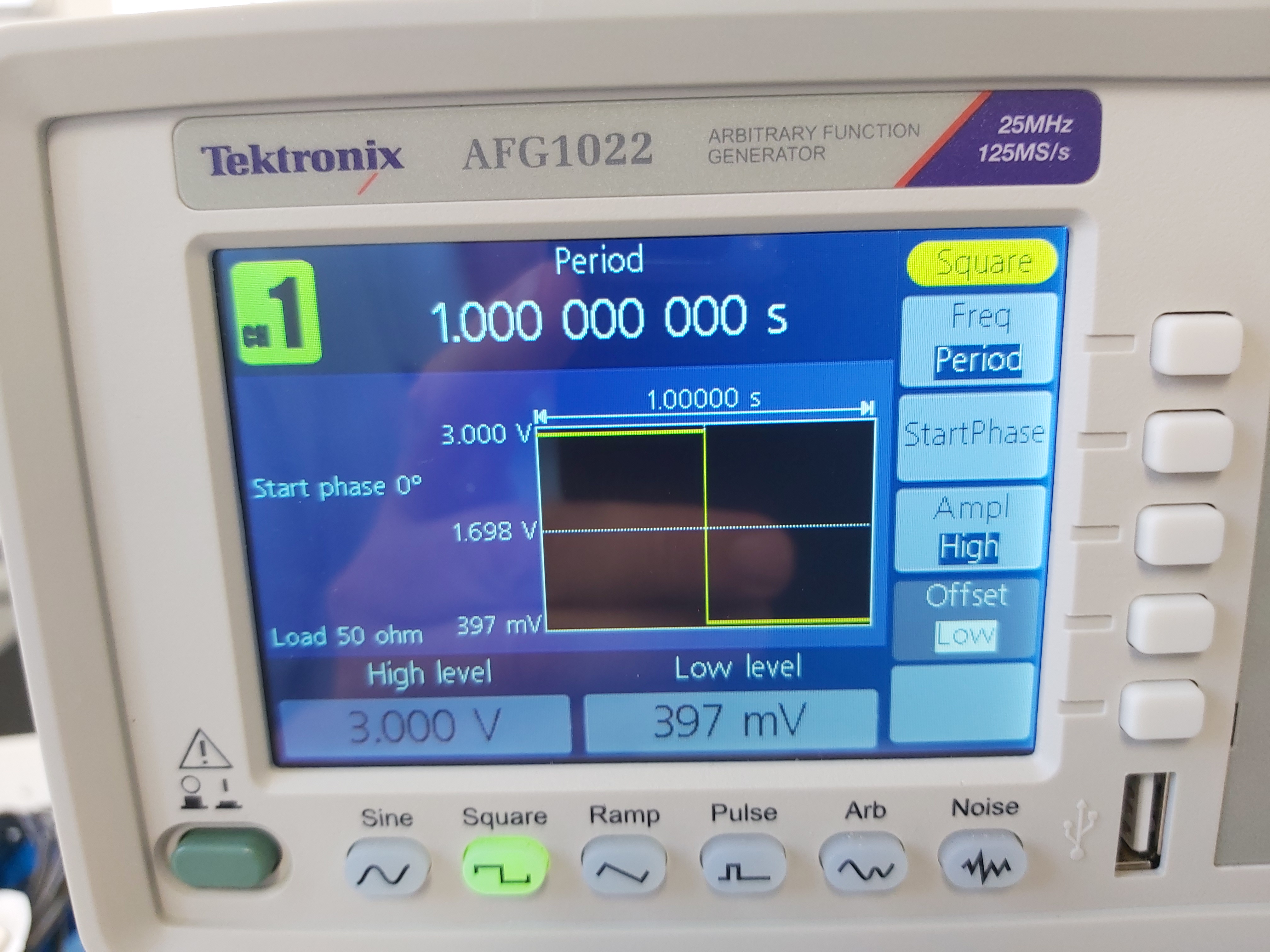
YELLOWISH: V_SUP
GREEN: OC

Normal Start
Failed start.
Anyone seen this? found a workaround?
Thanks,
André