This thread has been locked.

If you have a related question, please click the "Ask a related question" button in the top right corner. The newly created question will be automatically linked to this question.

UCC28070: Current saturation

Part Number: UCC28070

Hello,  

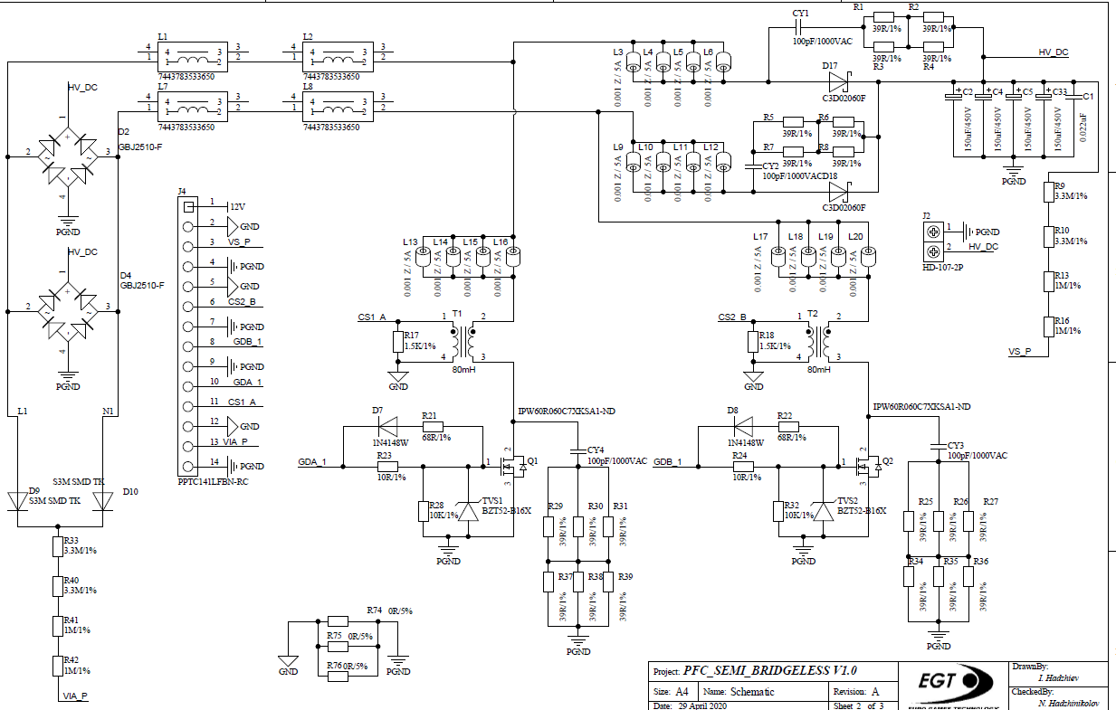
I have designed two semi-bridgeless PFC - one that works on 200 kHz and one on 90 kHz. 

The one that work on 200 kHz is just fine, but i have a problem with 90 kHz design

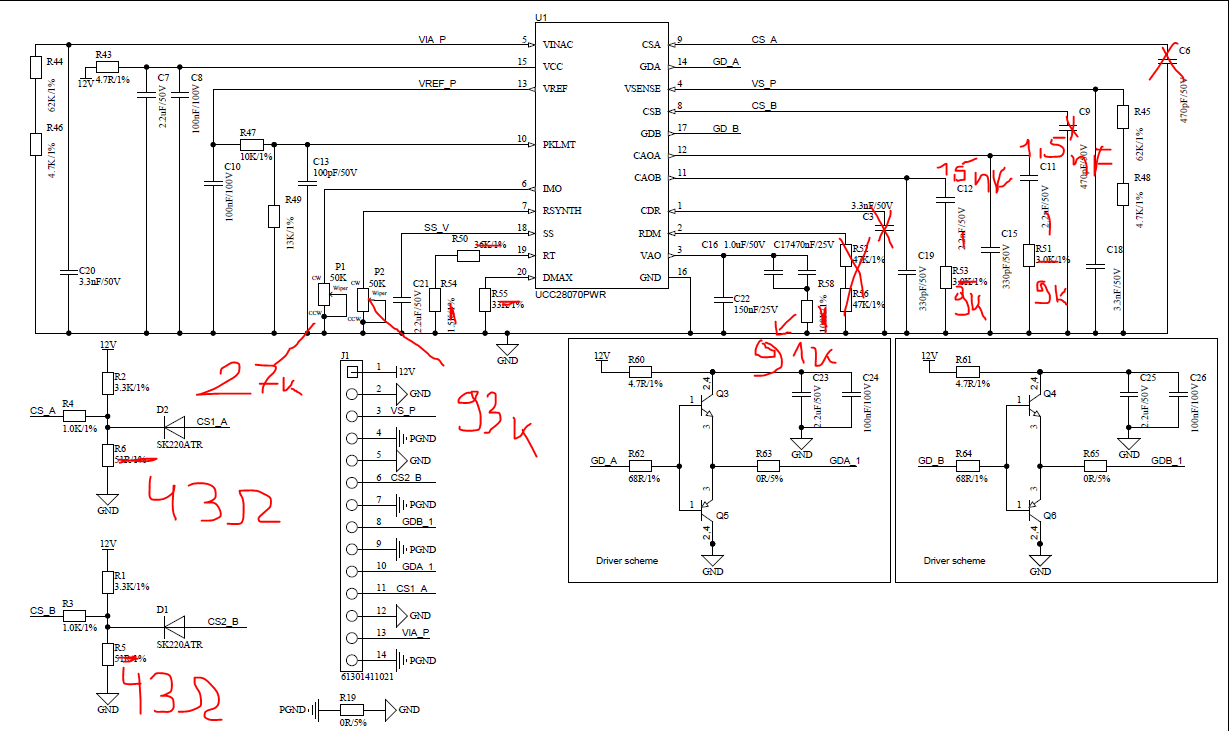
I have attached schematic with the input voltage and load conditions. 
the oscillograms shows  the inductor current and it seems like the inductor is going to saturation - the input rms current is 5,45A and inductor peak current should be 7,7A, but it jumps up to 10,7A  also the inductors generate noise that i can hear. 


I have attached the input current diagram and also the output voltage is regulated fine i have tested it on various loads. I have to mention that there is no saturation with 230V input. 

Regards 

various

  • Hello,

    When it comes to magnetic saturation there are two conditions that can cause issues.

    1. The volt seconds across the magnetic is not equal.
      1. In a peak current mode boost this is generally not an issue.
      2. If you added to much filtering to the VS pins then this can become an issue. If this is the case just decrease the current sense filtering capcaitors.
    2. The magnetic was not designed to store enough energy and saturates with the average current you are putting through it. 
      1. Check your magnetic specifications to make sure the saturation current is well above your average and peak current of your design.
        1. If it is not select another magnetic.

    I could not see your schematic if these recommendations do not solve your issue.  Please, reply and attached the schematic in a format that I can view?

    Regards,


  • Hello 

    the problem is not with the filtering capacitor also i tested the inductor magnetic and there is no saturation on 10A RMS ( attached picture ) 

    1. What do you mean by V.sec is not equal ? 
    2. Could incorrect measured feedback compensation circuit be the reason for that ?  

    The schematics are attached also: 

    Regards 

  • Forgot to mention the inductors that i am using are not those that are written on the schematic,  they are custom made and the inductance value is 260 uH 

  • Hello,

    Inductors saturate with DC voltage.  I thought your inductor were saturating because there was something wrong with the timing.  If V1*t1 when the inductor is being energized is equal to (Vout-V1)*t2 when the inductor is deenergizing the inductor will not saturate.  You have verified the inductor is not saturating.

    You have a picture with a box showing a constant voltage of 30 V.  Is that a constant voltage load? 

    What is your input and output power requirements?

    What are your test conditions?

    The following link will bring you to an excel design tool, where you can enter your input and output power requirements to double check your design as well.

    Regards,