A related question is a question created from another question. When the related question is created, it will be automatically linked to the original question.
If you have a related question, please click the "Ask a related question" button in the top right corner. The newly created question will be automatically linked to this question.
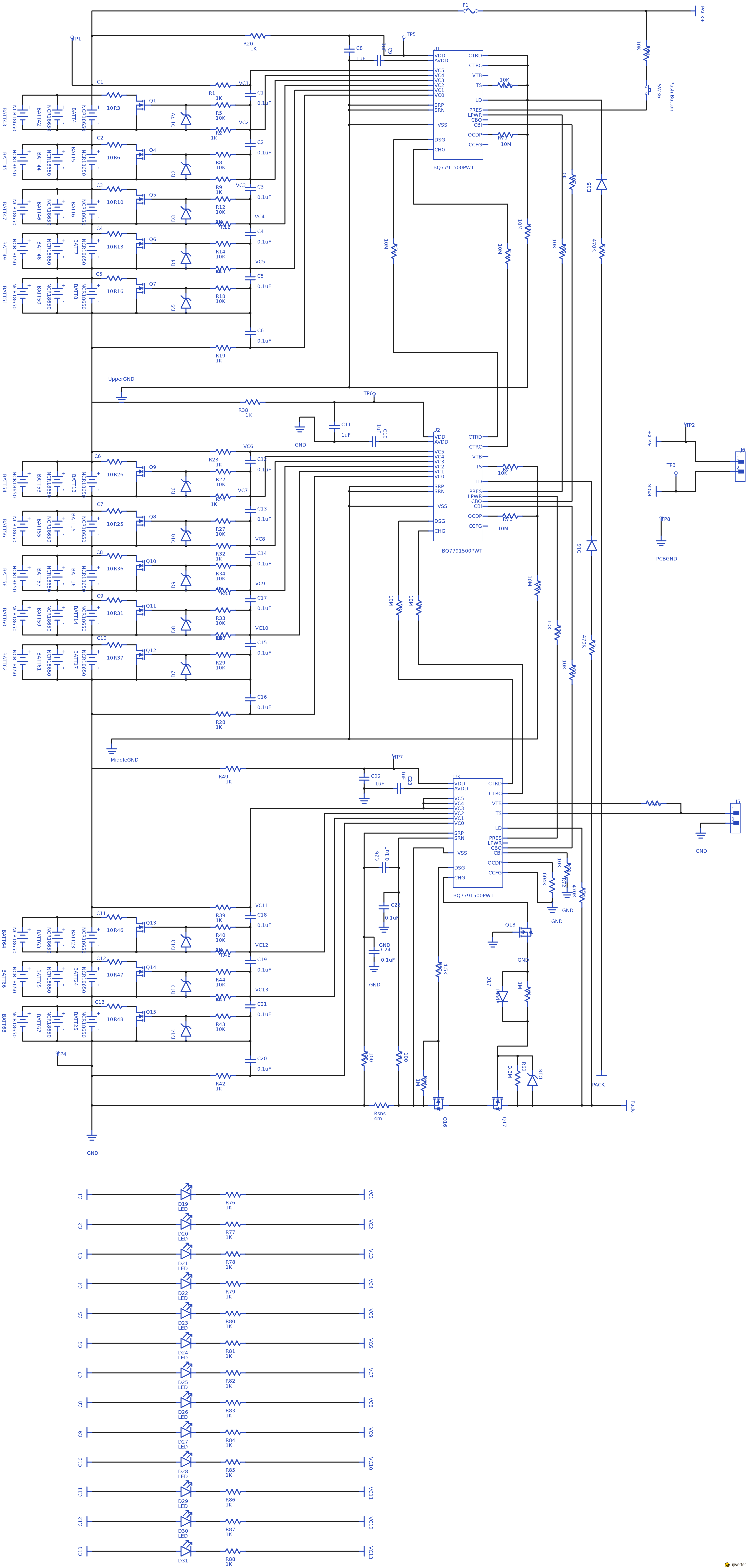
I see some things that need to be corrected in the schematic. I recommend you make these corrections and send the new version back for review once more:
The same Gnd reference cannot be used for each device in the stack. You should have a Gnd, Gnd_middle, and Gnd_upper. Please refer to this BQ77915 stacking app not for an example schematic: https://www.ti.com/lit/an/slua906/slua906.pdf
R54 (LD pin resistor) should be 470k (instead of 470)
There are components missing from the sense resistor pins. Please see section 10.2 in the datasheet - there should be series resistors and filter capacitors included (https://www.ti.com/lit/ds/symlink/bq77915.pdf).
The bottom device is configured for 3 cells. This should use VC0 - VC3 for the cell connections. See datasheet figure 9-11 for an example connecting 3 cells.
Make sure the refer to the datasheet example and the stacking app note example to double-check everything. Then send it to me once more and I can help look at the final schematic.
This looks much better. I checked with a colleague and they suggested connecting 5-4-4 cells to each device (5 to top device, 4 to middle, 4 to bottom device) as a better option to 5-5-3 to distribute the cells more evenly.
Also, it is not clear if the middle ground and upper ground are connected to the right point. They should be connected to the bottom of the lowest cell in that group.
As per your recommendation, I have changed the cell distribution to 5-4-4 pattern. Kindly review the final schematic. Also, let me know if the fuse position and the LEDs for cell balancing are correct.
The middle ground and upper ground are now connected to lowest cell in that group via flag (Schematic limitation). Please let me know if this is correct.
Also I want to know the maximum current BQ77915 can support.
The ground connections are correct. The LEDs are not needed - these are only included on the EVM to help the user see that balancing is working while evaluating the device. They are normally not included in a real battery.
Thank you for the feedback. Please let me know the maximum current Bq77915 can support. Like voltage requirement is 10.8V to 72V but what is the current requirement?
Sorry I missed the question about current before. The BQ77915 does not have a maximum current limit because it is just monitoring the voltage across the sense resistor. You need to select the sense resistor value carefully for the current you expect in your application.
There is a good example in Section 10.2.2 of the datasheet for selecting the sense resistor value. You need to consider what current values you want for OCD and SCD protections. The design example shows how to do this.
Thank you for your feedback. I also want to know whether using the external cell balancing is correct in my case. My charge current is 5A and considering the 10 percent termination current, cell balancing current is calculated as 500mA.
I am not sure on the calculation of the cell balancing current. Even went through the cell balancing video. Can you please guide on this.


