This thread has been locked.

If you have a related question, please click the "Ask a related question" button in the top right corner. The newly created question will be automatically linked to this question.

TPS25942A: PGOOD, and general behavior when V(IN) < 2.7V in power muxing applications

Part Number: TPS25942A

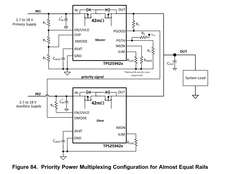
I have read the datasheet and the Application note slva811. My application is power muxing with priority similar to what is shown in Figure 84 of the datasheet. I have selected this mode in an attempt to work around the bug where the tps25942 need 238mA reverse current before blocking the internal mosfet. 

In Figure  84, the signal PGOOD is used to switch priorities to the slave when the Primary supply fails. That is true when IN1 falls down to 2.3v. But when IN1 reach 0v, the master TPS25942 has no more power to drive PGOOD low, and the pull-up resistor will bring PGOOD high, and also the DMODE pin of the slave TPS25942. Am I wrong? Is it possible that the TPS25952 can be powered by its OUT pin too so it would be able to drive PGOOD low even when V(IN)=0? 

Do you have other devices which are better at implementing true ideal diode and that do not have 238mA back current before switching OFF?

Thanks for your help

GV

  • Hi Gilbert,

    The image you have shared has not uploaded properly.

    Can you please use the attachment option and upload the image in .png format.

  • Here is the image that did not upload properly in my initial message.

  • Hi Gilbert,

    Yes, your understanding is correct.

    You can pullup PGOOD to IN1 so that the PGOOD is pulled low when IN1 is not present.

  • Hi Praveen,

    Unfortunately, connecting the pullup PGOOD to IN1 will not work in my application. Because IN1 is supplied by a wall transformer that could be disconnected live. When IN1 is suddenly floating, the master TPS25942 that was conducting will remain ON. The Out node will feed the IN1 node, and since the back current is much less than 238mA, the master TPS25942 has no way to turn itself OFF.

    I think it is an annoying flaw of this family of hotswap controller with reverse current protection. The scheme works only if the input power sources remain connected and also they must present a low resistance when OFF in order to draw the 238mA reverse current needed to turn off the ideal diode.

    In future hotswap controller with ideal diode you should try to fix this issue. Analog Devices has a nice solution in their ideal diode ICs. When the current is flowing in the forward direction, a small voltage drop accross the mosfet is forced. If the current tries to reverse direction, the small voltage will collapse and fall toward zero. At this moment, the device will turn off the mosfet. It is a bit more tricky to control the mosfet than your current devices, however it needs 0 mA of reverse current to turn OFF the mosfet.

    Thanks for your help

    Gilbert Vellet

  • Hi Gilbert,

    Thanks for your feedback. We are coming up with next generation device of TPS25942 which will have true zero reverse current blocking functionality.

  • Hi Praveen,

    Please do keep me informed of when this next generation of TPS25942 is going to be available. I am very interested for future projects.

    Best regards,

    GV

  • Hi Gilbert,

    Thanks for your interest in TI devices.

    We will keep you posted on our latest products.