This thread has been locked.

If you have a related question, please click the "Ask a related question" button in the top right corner. The newly created question will be automatically linked to this question.

TPS2121: OUT only 4.5V to 5V when IN1 and IN2 are between 15V and 16.8V

Part Number: TPS2121

Hi there,

We have added TPS2121 in our camera system to switch between 2 16.8V battery packs one among which powers our system at a time.

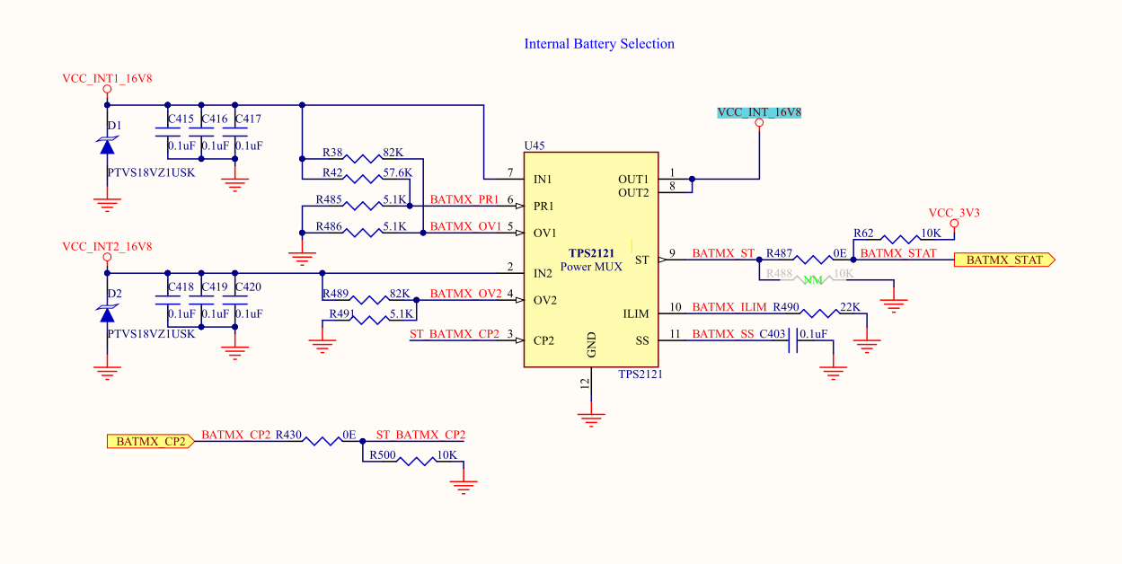
VCC_INT1_16V8: Battery Input 1

VCC_INT2_16V8: Battery Input 2

VCC_INT_16V8: TPS2121 Output to 3-Channel Power Mux Battery Input-1

BATMX_CP2: 3.3VIO GPIO signal controlled by processor.(Initially 0V due to pull-down).

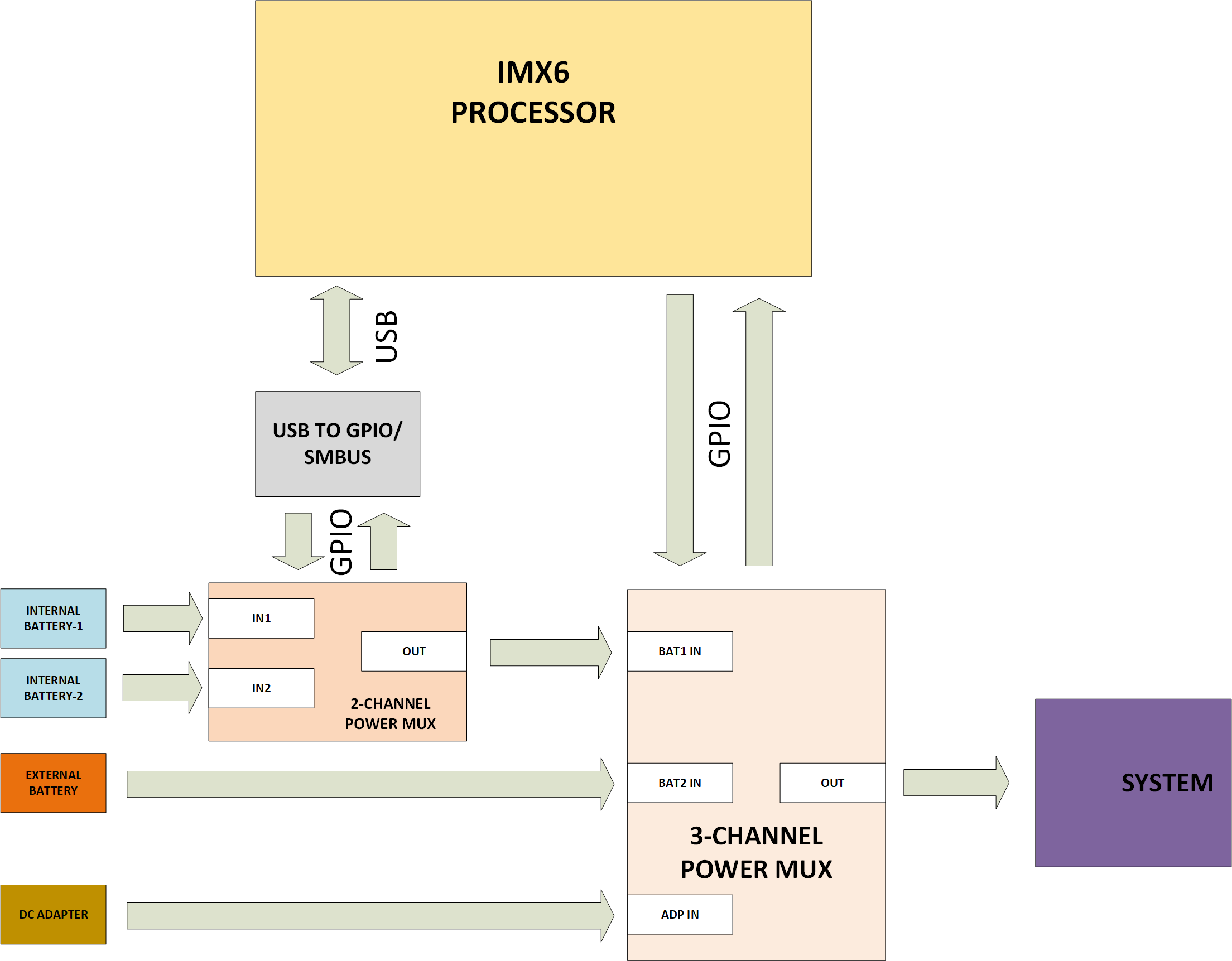
We observed that when only the Internal batteries are connected to the system, the system is not powering up.

As we inspected, found that VCC_INT_16V8 is between 4.5V and 5V only.

We ensured that VCC_INT1_16V8 and VCC_INT2_16V8 are both between 15V and 16.8V.

The voltage at CP2 was 0V.

The ST pin was LOW.

Can anyone help out why this occured. Is there anything to take care?

Thanks in advance.

Emil

  • Hi Emil,

    Could you please provide scopeshots that describe this issue? Is this event repeatable on more than one TPS2121 device? Does this only occur with the internal batteries connected or do other sources cause this drop in voltage? When you have external sources connected does the system work as intended?

    I also am unable to figure out your CP2 circuit. Where does the BATMX_CP2 node come from?

  • Hello Shreyas,

    We probed the voltage at SS and VOUT pins and noted that the voltage is switching there.

    At SS pin, the voltage is toggling between the around 13V and 0V at a similar frequency of  3.205Hz. This was when we used 1uF capacitor for SS.

    Earlier, when we used 0.1uF cap, the switching frequency was higher.

    At VOUT pin, the voltage is toggling between around 3V and 0V at a similar frequency of  3.125Hz. This was when we used 1uF capacitor for SS.

    Earlier, when we used 0.1uF cap, the switching frequency was higher.

  • Hi Emil,

    Could you please provide the following scopeshot:

    Ch1 - VIN1

    Ch2 - VIN2

    Ch3 - VOUT

    Ch4 - IOUT

    I assume CP2 is held low and VIN1 is being passed through to the output.

    It looks like the device is trying to startup but is failing to do so. Does this behavior change when you use external sources? Is this issue only limited to the internal batteries?

    Also, another test to do is to eliminate one of the batteries and check if the device correctly starts up with only one source.

  • Hello Shreyas,

    I shall probe all these together in different channels and share.

    Yes, CP2 is held low.

    Once we power the system up using external battery or DC adapter, this output from TPS2121 becomes stable.

    I tried with only one internal battery connected at a time, but the result was same.

  • Hello Shreyas,

    Please find the waveforms.

    IN1: Internal Battery Input 1

    IN2: Internal Battery Input 2

    OUT: TPS2121 Output

    Vss: Voltage at SS pin

  • Hi Emil,

    Thank you for the waveforms. To me this eliminates any sort of UV or OV fault occurring from the internal batteries. 

    Since the system works as intended from external supplies, I believe that your switchover settings are correct.

    Please confirm: OVx is set around 18V and PR1 switchover is set up at around 13V. Your intention is to do manual switching by using CP2 pulled high or pulled low.

    My suspicion is that there may be a thermal event(current limiting) occurring in the device during turn on. Since you have confirmed that this behavior still occurs with only one supply can you re-run the test once more with only the external battery connected to VIN and CP2 pulled low?

    Can you please probe the following signals:

    Ch1 -> Vin

    Ch2 -> Vout

    Ch3 -> ST

    Ch4 -> I_in or I_out

    The SS pin is showing that the device is soft starting every "turnon" phase. A current waveform will help us confirm what the device is experiencing during each failed turnon. 

    Thank you very much for providing these scopeshots and troubleshooting this system.

  • Hi Shreyas,

    Yes, OV1 and OV2 are set at18V and PR1 switchover is set up at around 13V.

    We have designed for the switchover from Internal Battery1 to Internal Battery2 by driving a logic High(3.3V) at the CP2 pin by our controller. Initially, this pin is pulled low using a 10K resistor.

    We also suspect if it is a current limiting case by the TPS2121. Whatever supplies(battery pack or DC power supply output) if we connect to the IN1, IN2 or both IN1 and IN2 of TPS2121, we can observe the output of TPS2121 is ramping.

    We suspect if the 3-channel power mux to which the output of TPS2121 is connected is initially trying to draw some current and TPS2121 is preventing that and the ramp occurs then.

    Once we connect any power supply or battery to any of the other 2 channels of the 3 channel power mux, this initial current may be drawn from it and so the output of the TPS2121 becomes stable as no current is being driven.

    Is there any way to avoid this current limiting feature of TPS2121?

    If we keep SS pin of TPS2121 open, is there any issue?

    We shall try to probe the current value.

    Thanks.

    Emil

  • Hi Emil,

    There is no way to disable the current limiting feature on this device. It may be possible to reduce the ILIM resistor to 18kOhm which would set the highest current limit but it cannot be disabled. 

    It is possible to float the SS pin. This would results in the fastest slew rate for the device. Do note that in the case of any inrush or capacitive load, large inrush currents could flow which could damage the device and the downstream load.

    You have an interesting hypothesis about the 3-supply PMUX. I am not familiar with this device but we might be able to confirm this behavior if you are able to provide a current waveform in two cases with the previous channel outputs that I asked for:

    1. no other supply connected to 3-way PMUX

    2. one other supply connected to 3-way PM

    Thanks once again.

  • Hello Shreyas,

    Thanks for the clarifications.

    As we donot have a current probe, shall see what is possible to probe the current.

    Shall share the waveforms on Monday.

    Other than the current limit (currently 4.5A) set using Ilim resistor, is there any other internal feature which prevents system from supplying enough initial current as our system is off and only the 3-channel power Mux(Max1538) will be using some current(probably won't be high as 4.5A).

    We had tried placing a 100uF capacitor at the output of TPS2121 and the voltage is almost stable then. But then, the 3-channel mux is not driving on the required mosfets to enable the power path from TPS2121 out to system.

    Thanks.

    Emil

  • Hi Emil,

    Only a fault would cause TPS2121 to stop passing current from input to output. These include OV,UV, thermal shutdown(absolute and relative) and current limit(which is thermal in nature).

    There might be a pull of current from the three input powermux that is may be triggering a thermal fault or current limit fault. 

    The current waveform will help us narrow this down.

  • Hello Shreyas,

    Currentl, we also suspect the same. Donot have an option to check the current without damaging a PCB. Shall try it later.

    Meantime, we need a clarification regarding the TPS2121 chip.

    Does TPS2121 support hotswap of power sources?

    By hotswap I mean, I have an External battery connected to IN1 channel of TPS2121 and an Internal battery to IN2 channel of TPS2121.

    As I have connected the CP2 pin to the processor and have added a 10K pull-down to GND to the same(IMX also drives it low once system powered up), system power up from External battery.

    The customer may randomly remove the External Battery and the TPS2121 should switch to Internal Battery. Will TPS2121 support this?

    Thanks.

    Emil

  • Hi Emil,

    TPS2121 can support external supplies being hotplugged but there is no protection against voltage spike events. Please refer to section 10.7 on the datasheet for more information.

    We recommend using some sort of suppression (such as TVS diodes) in the event there are voltage spikes over the recommended voltage ratings on the input.

  • Hello Shreyas,

    Thanks for the quick response.

    We had added the 18V TVS diodes as suggested in the app note.

    Meanwhile, as we practically checked removing the power source from IN1 channel, the system is not switching to power source connected to iN2 channel.

    Why would this happen. Is of CP2 driven low a cause for not switching to IN2 even in hot removal of IN1?

    Thanks.

    Emil

  • Hi Emil,

    What is the voltage of CP2 during this hotplug event? I thought you were manually switching the input rails using CP2. If CP2 is pulled low, the device will prioritize IN1 until that rail has discharged under UV before making the switchover. The device does not pull CP2 low on its own. 

    During an auto switchover event, the output voltage has to fall below the input voltage on the second channel before the switchover can occur. This is done to avoid any back flow of current from a higher voltage on the output to the input supply on VIN2.

    What is your intent with this device? Manual switchover or auto switchover? 

  • Hello Shreyas,

    Thanks again.

    The CP2 pin is held low to give priority to IN1.

    But when IN1 is removed by the user without informing the system, we actually need TPS2121 to switch to IN2 automatically as we've set 13V as UV for both IN1 and IN2 channels.

    But we observed it doesn't switchover and the system fails.

    We need a solution for this. Can this be solved if we keep CP2 open without driving anything?

    Also, will us driving CP2 low from the processor prevent the TPS2121 from switching to IN2 even if IN1 goes below its UV set at 13V during the hot removal of this source?

    Thanks.

    Emil

  • Hi Emil,

    Please refer to Table 3 for the operating modes for TPS2121. When you pull CP2 low, there is no priority reference for the device and so the device will work in different modes that compare input voltages. (VREF and VCOMP)

    As the voltage falls, PR1 is still larger than Vref, and IN1 continues to be prioritized. The device is in VREF mode. 

    Depending on how the PR1 voltage is set, one of two outcomes may occur:

    1. PR1 remains over VREF for the duration that VIN tends below UV(2.8V). The device recognizes the invalid input and then soft starts into IN2. This is a slow switchover with soft start.

    2. PR1 falls below VREF (and IN1 is still valid) and the device transitions to VCOMP mode. The device then compare IN1 and IN2 and if IN2>IN1 the device will begin the switchover(slow) to IN2. The device waits until the output voltage falls below IN2 and then turns on the channel to avoid any reverse current flow.

    If you would like the device to utilize fast switchover from IN1 to IN2 (still will wait for the output to fall below IN2 to make the connection), you will need to use the device in XCOMP or XREF mode. Please refer to this report to see how to perform seamless switchover with TPS2121: https://www.ti.com/lit/ug/tidue50/tidue50.pdf