This thread has been locked.

If you have a related question, please click the "Ask a related question" button in the top right corner. The newly created question will be automatically linked to this question.

TPS65135EVM-265: Ripple reduction

Part Number: TPS65135EVM-265

Hi sir,

I have a problem on debugging schematic on TPS65135RTER.

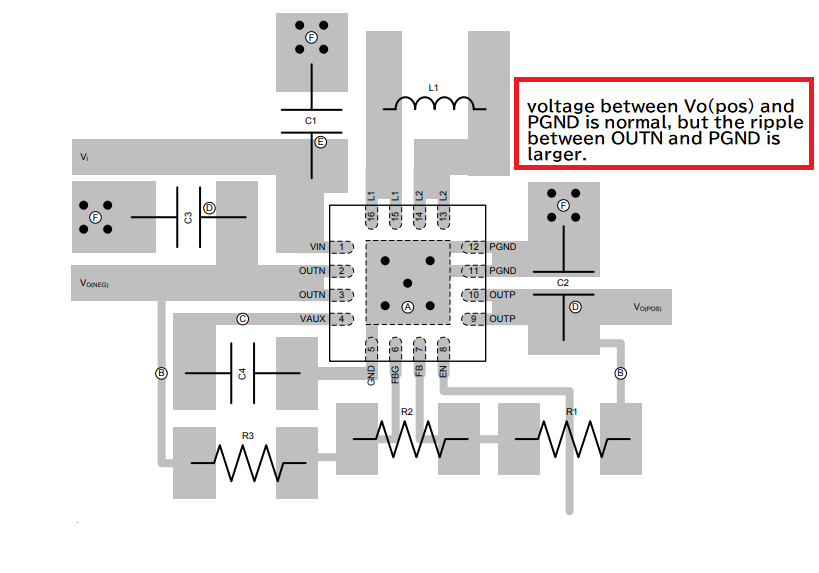
I find the ripple is clear between OUTP and GND, because we use it in high frequency, so the waveform will be distorted once there is a ripple. 

How to improve and reduce the ripple?

Ripple

Thanks,

Regards,

M

  • Hello,

    I am not sure if I fully understand but from your picture, it seems that ripple is smaller and acceptable when measured with reference to ground on the same side of the board as OUTP but is larger when measured with reference to ground farther away from OUTP output. This should be expected as the ripple will be bigger because of the added parasitic resistance and inductance in the farther path. To get true ripple voltage, ripple measurement should be taken right at the output capacitor of the converter i.e. across C2 for OUTP and across C3 for OUTN.

    Kind Regards,

    Liaqat