This thread has been locked.

If you have a related question, please click the "Ask a related question" button in the top right corner. The newly created question will be automatically linked to this question.

TPS79901-EP: TPS79901 Feedback Resistors

Part Number: TPS79901-EP

We are using TPS79901 regulator for generating variable output voltages. 180K we are using as R1 and 1.8M as R2 for generating 1.3V output voltage.

For generating other higher voltages we are using parallel combination of resistors in parallel with R2.

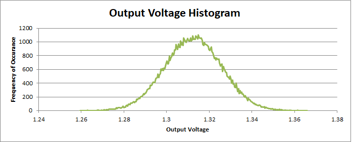
We are facing issue in dropping the output voltage at the LDO output. Can you check whether the above feedback resistor values are suitable or not for this LDO.

  • Hi Siburaj,

    Those resistors are fine.
    In most cases any value of resistance can be applied to linear regulators, the issue is the leakage current out of the feedback pin which multiplies against one setpoint resistor and modifies the output voltage.  Since the leakage current is very small in modern LDO's (well under 1uA in many cases) this effect is not always measureable.  In your case the statistical analysis suggests 1.3123V nominal with 13.4 milivolts of standard deviation.  So for a room temperature, sample of one, I would expect a setpoint within 1.3123V +/- 0.0134V. 

    What voltage are you seeing instead of 1.31V?
    Can you review the board and make sure it is clean?  Be sure that there are no leakage paths due to flux from soldering on the board.
    Are you measuring the output voltage without a load current attached?  With a load there will be an IR drop on the PCB, which can lower the measured setpoint.

    The statistical analysis as plotted in a line chart is shown below.

    Thanks,

    - Stephen

  • Hi Stephen,

    Thanks for your quick response.

    What voltage are you seeing instead of 1.31V? ->  0.7V.

    Actually at the bottom side (R2) we are connecting 7 resistors in parallel and have jumpers to isolate each resistors from ground to generate different output

    voltages from 1.3 to around 3.31V.

    Thanks & Regards,

    Siburaj D.S.

  • Hi Stephen,

    Can you look into the above circuit and make sure everything is fine. The resistors R560 from left end to R569 at the right end we are connecting to ground through a 2 pin hear generating different voltages.

    Regards,

    Siburaj

  • Hi Siburaj,

    Just to be clear, with none of the jumpers connected (which should give you 1.3V from R556 and R560) you are seeing 0.7V on the output?

    Can you review the board and make sure it is clean?  Be sure that there are no leakage paths due to flux from soldering on the board.

    What is the measurement using a DMM from the FB pin to RF_GND?

    Thanks,

    - Stephen