This thread has been locked.

If you have a related question, please click the "Ask a related question" button in the top right corner. The newly created question will be automatically linked to this question.

LM5176: power instability when crossing between boost and buck thresholds

Part Number: LM5176

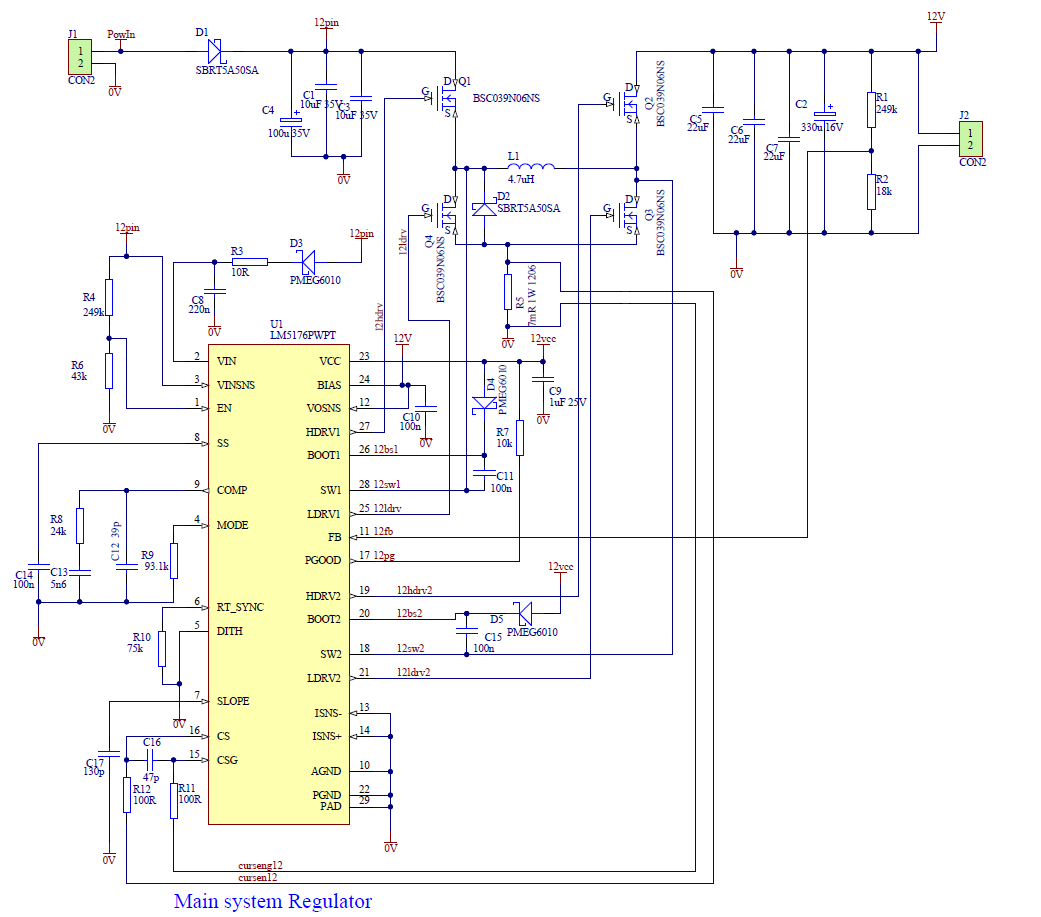
Hi, I've have a problem with power dissipation at the point at which the regulator switches from buck to boost (and visa-versa) on low load. The regulator was designed in  Webench to give 12V at up to 4A  with an input of between 8V and 30V. We have basically copied the Webench layout (but shrunk  it to reduce board area). This issue occurs when with a 12V 5mA load (2K2 resistor)  and the incoming supply it stepped in 1 v steps (with time to read meters and record result - by writing on paper -  between each step. as the input voltage reaches 12V the input supply current goes up significantly (150mA plus from a much lower value of 10ish mA) recovering to the 10ish mA when passed the threshold  (ether supply going up or coming down) at the same time power dissipation in the inductor goes up markedly (it gets hot) which is surprising considering the low currents in both input and output. Adding a vastly increased output capacitor (2000uF) helps in that the input current peak can be brought down to 80-100 but the inductor is still hot to touch. This suggests some kind of instability at the swop over threshold (from buck to boost) .

So the question is:- what should we checkout / trim to improve stability

(the application is for a agriculture based project that could be powered from several sources , A 12V lead acid battery , a 16.5V power pack , a four cell lithium ion battery , a 24V lead acid battery , or a solar panel or some combination of these.)

  • Hello Steve,

    Please share your schematic.

    My first check would be to take the LM5176 Design Calculator to re-check the external components.

    Please check the output voltage with an oscilloscope. You can as well have a look at the comp pin and the current sense resistor voltage.

    It sounds as if the converter is sending current back and forth.

  • Hi Brigitte, Thanks for the reply. I have redone the calculator and the values appear to be sound, I have even done the calculations manually with the same result so all seems correct.

    It was my thoughts also that the regulator is either sending current back and forth or perhaps a switch timing issue resulting is upper fets and lower fets being on to some extent together creating some kind of limited shoot through.

    I have varied a few of the components in the slope filtering and compensation to see if that had any bearing and could see no material effect to this issue, hence posting.

    I'm sure the devices must work ok otherwise there would be many more reports of such issues, and was hoping that someone else had seen the issue and figured out how to fix.

    looking around the chip with a scope shows signals that I would expect.

    I'll have another go with the calculator just in case I missed something and I'll report back

    Regards Steve

  • Hello Steve,

    You schematic shows a switching frequency of 112kHz. Please check if the problem gets better when using a 15uH inductor.

    If you want to keep this low inductor value, I recommend to increase the switching frequency to 400kHz by reducing the RT to 20 kohm.

  • Hi Brigitte, Your suggestion to increase the frequency resolved the issue thank you.

    In the end I reduced the inductor further  to 3.3uH (space constraints) and up the frequency to approx 500Khz (RT=15K) and the PSU is now stable over the whole range of supply voltages and loads, with a Measured efficiency of 95% or more over the main  power band.