This thread has been locked.

If you have a related question, please click the "Ask a related question" button in the top right corner. The newly created question will be automatically linked to this question.

UC2843: Audible Noise and High Temperature Problem during dimming with PWM on External LED Driver

Part Number: UC2843
Other Parts Discussed in Thread: TL431, UCC28C45

Hello,

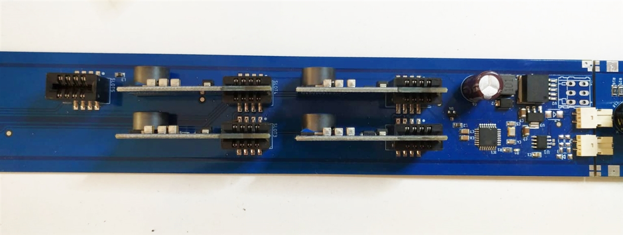
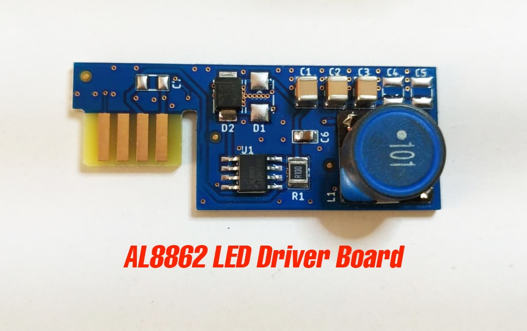
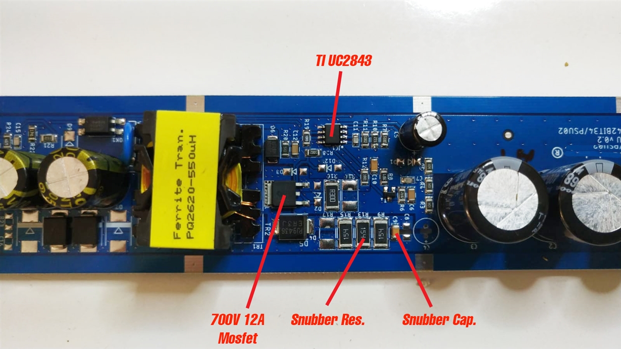
There 4 channels to drive 4 different colors LED. AL8862 (Diodes Co.) is used to drive LEDs with PWM dimming technology (PWM generation with ATMEGA328 Microchip).  And on the power supply, We use TI UC2843 IC on the power supply to get 55V 1.2A output. 

1) When we drive (with AL8862 without PWM) LEDS as 10-20-30-40-50W etc..., there is no audible noise on snubber capacitor and high temperature on the Mosfet and snubber resistors. It works perfectly!

2) If we drive (with AL8862 WITH PWM) the same watts (10-20-30-40-50W ) for dimming LEDs, There is audible noise on snubber capacitor and high temperature on Mosfet and snubber resistors. so, MOSFET deteriorates due to high temperature.

IC UC2843 with PWM (AL8862)

VCC: 25V (max measured)
Visense: 0.45V (max measured)
Vfb: If we drive 2 channels with lower PWM value, We measured about 3V, If we drive fully both channels, measured 2.5V. AND If we drive 1 channel with lower PWM or full PWM, We measured 2.5V

* To see THERMAL RESULTS, Please check the PDF attachments.

* Please check the attachment to see power supply schematic

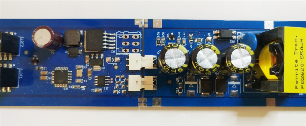
* Please check the attachment to see photos of boards

Your answers are really valuable to resolve that problem. 

If you need another measurement (with multimeter or oscilloscope), please tell me.

Thank you very much

PSU Diagram.pdf0458.Transformer.pdfDriver LEDs with AL8862 WITH PWM.pdfDriver LEDs with AL8862 without PWM.pdf
  • Is there any engineer to help us to resolve the problem?

    Thanks

  • Hi,

    From a quick inspection of your control loop components around the TL431 I suspect your loop is unstable. have you plotted the bode (gain/phase) plot for the control ?

    I have attached a PSPICE file that you can use to simulate the Flyback topology, you can use the free TI SPICE tool to run this file. You will need to modify the component values to match your circuit. The transient file will simulate the circuit in the time domain and the AC file will simulate the circuit in the frequency domain.

    You can also use the TI power stage designer tool which will give you some feedback component values around the TL431 as a start point.

    Please also read the UCC28C45 datasheet which goes through a control loop design example.

    Regards

    PeterUCC28C45.zip

  • Hi Peter

    We simulate these tools according to UCC28C45, right? Results will be suitable for UC2843?

    Thank you

  • Peter

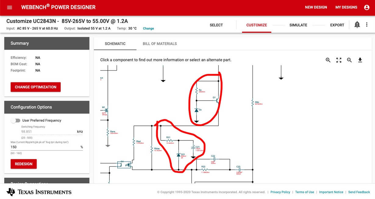
    Our power supply's output values are 55V, 1.2A. According to webench design, there are some components around TL431, but when we check datasheet typical application, they are not there. They are necessary or not for the control loop? 

  • Hello Omer,

    The components Q1, Rz and Dz are used to provide a necessary low-voltage bias source for the TL431 shunt regulator.  It cannot be biased directly from the 55-V output, which is too high for the TL431.  Typical values for Dz are 12V or around there.  Rz is sized to bias Dz and provide adequate base current to Q1.

    R21, D21, and C21 form an optional soft-start network.  At initial power up, C21 is discharged to 0V, and as Vout rises, it starts charging C21 mostly through the Rled,  opto-diode, and D21 path.  Charging C21 keeps feedback current high, so power output is low and start-up is "soft".  Once Vout is finally up to regulation, R21 continues to charge C21 up to the bias source, to keep it from interfering with TL431 transient activity at the opto-diode node.  R21 is sized to be a high value to avoid interfering with the soft-start rate.  C21 value is large and sized empirically to achieve the desired Vout slew rate. 

    Regards,

    Ulrich

  • Hi again,

    I have tried several times different methods to resolve my problem. If components around TL431 occur this problem, I need your help to select the true values of components.

    I am not engineer, I really do not know lots of technical things on the power supply. We do not have any time to finish our order for a project. But We have been working on this problem for 2 months. 

    We have tried to use your software to find true values of the control loop, but It is really difficult for us to use. 

    Please just tell me which information you need (transformers, optocoupler, FET,...etc), Hope, you help us to resolve the problem.

    Thank you very much

  • Hello Omer,

    A step-by-step design procedure for loop compensation is shown in the application section of the UCC2843 datasheet.  If you follow this closely, it should result in a stable system.

    Meanwhile, I will refer this thread to someone in the DC/DC group who should be able to help you more readily.    

    Regards,
    Ulrich

  • Thanks you Ulrich

    Trust me, I have tried all ways to resolve this problem. I have read datasheet tittles one by one but lots of them are unknown for me.  I have tried to use softwares but there lots of unknow terms  to find result. But I am really tired and no time to finish that power supply, just need your help for only control loop components.

    Beginning of this tittle, i sent lots of documents , if need more, please tell me. Waiting reply from you and your friend in DC/DC group

    Thank you very much

  • Hi Omer,

    It looks the E2E may not be a good place to continue. Can you please send to me an email and summarize the current situation based the existing E2E support and the issues you still have, to hong_huang@ti.com

    Let's work to resolve the issues in your design through email. I am closing this thread and waiting for your email and will go from there.

    Regards,

    Hong Huang