Hi team,
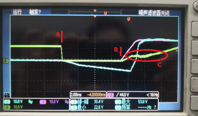
My customer is using the LM5067 now. The waveform is below.
CH2 (BLUE) is the LM5067 output side, CH3(purple) is the LM5067 input side, CH4(GREEN) is the GATE of the MOSFET.
A point , LM5067 UV , gate to low, B point, LM5067 UV recover, Gate to high.
1. The customer want to check the reason of the A point slew rate. in my opinion, the sink current is decided by sink current spec and gate driver resistor.
2. What's the reason of the C point? In my opinion, the C is the miller effect (miller plat).
Thanks.


