This thread has been locked.

If you have a related question, please click the "Ask a related question" button in the top right corner. The newly created question will be automatically linked to this question.

BQ40Z80EVM-020: Initial Setup for bq40z80

Part Number: BQ40Z80EVM-020
Other Parts Discussed in Thread: BQ40Z80, GPCCHEM

Hello,
1. Document SLUA848 (How to Complete a Successful Learning Cycle for the bq40z80)
defines:
"design Voltage = (number of series cells) x average cell voltage.
For example, a pack
with five cells in series might use Design Voltage = 5 x 3700 mV = 18500 mV"
and
"Term Voltage = 3 V x 5 cells = 15000 mV"
i.e Design Voltage should always be greater than Term Voltage

while in fresh loaded Firmware bq40z80_v0_04_build_5.srec(for 6S ChemID 0x1210 !), I found
Gas Gauging\Design Voltage = 14400 mV
and
Gas Gauging\Term Voltage = 21000 mV.

What does it mean and where is the truth?

2. In my setup for 6S LiFePO4 (ChemId = 0465),
according the recomendations in SLUA848,
I set the following values in Data Memory:
Gas Gauging\Design Capacity, mAh 2500 mAh
Gas Gauging\Design Capacity cWh 3600 cWh
Gas Gauging\Design Voltage 19800 mV
Gas Gauging\Dsg Current Threshold 100 mA
Gas Gauging\Chg Current Threshold 50 mA
Gas Gauging\Quit Current 10 mA
Gas Gauging\Term Voltage 12000 mV

Advanced ChargeAlgorithm\Term Taper Current 200 mA.
Is it really enough?

Do I need to change other chemistry specific settings, e.g:
Gas Gauging\FC\Set Voltage Treshold (4200),
Gas Gauging\FC\Clear Voltage Treshold (4100),
Gas Gauging\FC\Cell n Chg Voltage at EoC (4200),
and all other chemistry related settings?
Because, it is obvious that default Firmware values
are for LION chemistry.

In other words, what is complete setup set for bq40z80,
what need to be done before starting?

Thanks in advance,
Vladimir

  • Hello Vladimir,

    The Term and Design Voltages are values that you have to adjust yourself, don't base it on default values. What the SLUA848 document is saying is correct. Term Voltage is the voltage where the gauge will read a SoC of 0%, so it must always be less than the Design Voltage.

    I noticed that your Design Capacity in cWh is incorrect, it should be 2.5*19.8*100 = 4950-cWh.

    The Charge Term Taper Current seems to be dependent on your charger as explained in Section 3.2 of SLUA848. Yours I think is fine, as it indicates that it should be less than C/10.

    In order to start the learning cycle, you only need to change the values described in Section 3 of SLUA848, these are the only required ones in order to complete it. You would then adjust the other values based on your application. You can adjust the FC values, but I don't believe they would cause any issues with the learning cycle. 

    Best Regards,

    Luis Hernandez Salomon

  • Thanks for the answer, Louis.

    About design capacity

    why not 3.3 * 19.8 * 100?

    The battery is declared 3.3 V nominal.

    What about Chemistry?

    Should I change default mV settings anywhere?

  • Hello Vladimir,

    The cWh Design Capacity is based on the mAh Design Capacity and Design Voltage.

    You are already using 3.3-V with the 19.8-V value. Since you are using BQ40Z80 in 6s configuration, (3.3-V)*(6) = 19.8-V.

    So the cWh design capacity is calculated by: (3.3-V)*(6)*(2.5-Ah)*(100-centi) = 4950-cWh.

    I hope that helps.

    Best Regards,

    Luis Hernandez Salomon

  • Hello Vladimir,

    If you are talking about Chemistry ID, the best way to obtain one is by using the GPCCHEM tool. This would give you the best Chemistry ID for your cell stack.

    Could you specify what mV you are thinking of changing?

    Best Regards,

    Luis Hernandez Salomon

  • Thanks for answer, Luis.

    Sorry, by the end of the day, the chip ate my brains.
    So, here are the settings under suspicion:

    Protections
    CUV 0x4BC2 Threshold
    CUV 0x4BC5 Recovery
    CUVC 0x4BC7 Threshold
    CUVC 0x4BCA Recovery
    COV 0x4BCC Threshold Low Temp
    other mV....

    Permanent Fail
    SUV 0x4C49 Threshold
    SOV 0x4C4C Threshold
    VIMA 0x4C72 Check Voltage
    other mV....
    Advanced Charge Algorithm
    Low Temp Charging 0x4C9F Voltage
    ...
    Voltage Range 0x4CCB Precharge Start Voltage
    Voltage Range 0x4CCD Charging Voltage Low
    Voltage Range 0x4CCF Charging Voltage Med
    Voltage Range 0x4CD1 Charging Voltage High
    CS Degrade 0x4CEB Voltage Threshold
    CS Degrade 0x4CF1 Min CV
    Charge Loss Compensation 0x4CFE CCC Voltage Threshold

    Gas Gauging
    FD 0x4B74 Set Voltage Threshold
    FD 0x4B76 Clear Voltage Threshold
    FC 0x4B7A Set Voltage Threshold
    FC 0x4B7C Clear Voltage Threshold
    TD 0x4B80 Set Voltage Threshold
    TD 0x4B82 Clear Voltage Threshold
    TC 0x4B86 Set Voltage Threshold
    TC 0x4B88 Clear Voltage Threshold
    State 0x44D9 Cell n Chg Voltage at EoC
    IT Cfg 0x4A56 Term Min Cell V

    Regarding the GPCCHEM tool
    why should I use it if my battery is exactly corresponding the Chemical table?

    My problem is that Charge/Discharge cycles in Learning mode
    ends earlier than expected, so, the learning cycle never ends.

  • Hello Vladimir, 

    Could you share your .GG file so I may take a look at it? Also, can you also upload the log of your learning cycle?

    What is your LStatus during your learning cycle?

    You shouldn't have much issues in the learning cycle if you set-up the values described in the applications report(SLUA848). 

    Best Regards,

    Luis Hernandez Salomon

  • Hello,

    Now I'm at the beginning of initial discharge state.

    All data in attach.5_08_20.ZIP

  • Hello Vladimir,

    I'd recommend you use a discharge current of C/5. Which would be 500-mA discharge current based on your Design Capacity. It is recommended to use a discharge rate between C/5 and C/10.

    It seems that the initial discharge state was successful, as the LStatus is 4. Did you wait for at least 5 hours for the battery to relax after discharge? During this time there should be no current through the batteries. You'd let the battery relax until VOK and RDIS clear in the register screen and the REST bit is set.

    Best Regards,

    Luis Hernandez Salomon

  • Hello, Luis
    Thanks.

    I had to change my battery configuration to 5 cells, because cell 6 allways seem to be overcharged(above 4.2V).

    Now I'm in charging state and graph looks much flatter than before.

    Waiting for results...

    Regards,

    Vladimir

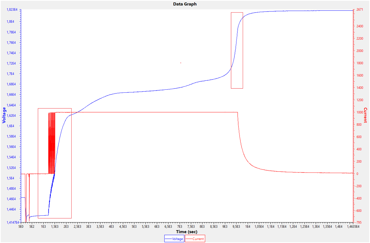
  • So, it seems that charge cycle finally completed normally.

    Two things surprize me:

    1. Initial On/Off oscillations at the beginning of charge.

    Maybe some protections activating?

    2. Anomaly rapid voltage increas near the end of charge.

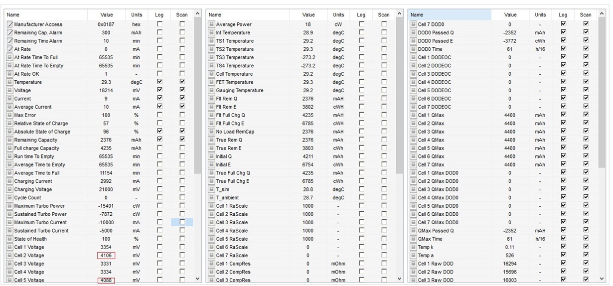
    I suppose it is because 2 cells (2 and 5) are weak.

    Am I right?

  • Hello Vladimir,

    Did you change your other values to support 5 cells instead of 6? During the oscillation periods, do you see any of the COV or CUV bits set? 

    Are these issues seen with other battery packs? I find it odd that the voltages in two of your cells are so widely different from the rest.

    I still see that your discharge rate is too high, your discharge rate should be between C/5 and C/10.

    Best Regards,

    Luis Hernandez Salomon