A related question is a question created from another question. When the related question is created, it will be automatically linked to the original question.
If you have a related question, please click the "Ask a related question" button in the top right corner. The newly created question will be automatically linked to this question.
The datasheet is asking to tie Pin 13 either to GND or REF. So there is no specs for threshold. Please just follow the datasheet to tie this pin to GND or REF.
REF pin voltage is measured with 1k ohm resistor and also shows the load regulation. So if < 1mA, or open, the REF load regulation is not within the datasheet. So make sure load REF with min load requirement.
If any of the pins break down or become open, then need to specify that pin, as not any pin has a same loading like REF.
Could you give me advice about Vref voltage? My customer measured Vref voltage that was 5.6V. The current is flowing over 1mA. What kind of anomalies are possible?
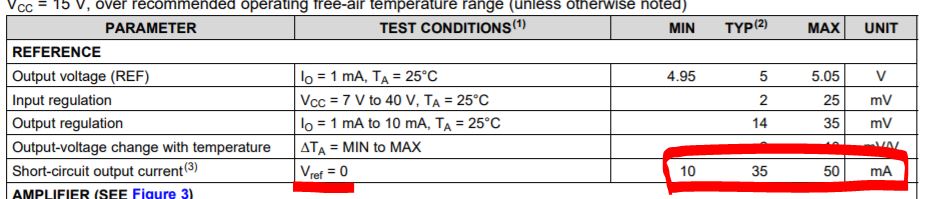
Based on datasheet, Vref should be in 4.95V to 5.05V on VCC = 15V when Vref pin Io = 1mA. If your test shows Vref not within the datasheet on the same operation condition, it is likely the IC on your circuit is somehow damaged or with some defects from possible damages. You can replace with a new unit to retry.
If IC not within specs, then you may contact your local TI sales, and ask to start failure analysis to see what possible damages or defects to be and help you to eliminate possible causes in your circuit.
Io from 1mA to 10mA Vref regulation is within 35mV so very small compared to 5V. If Io > 10mA, Vref is shutdown to zero. These are all in the datasheet. The Vref is in analog and no min/max on or off time. If you see on and off, it is likely you triggered short circuit, and you need limit your current in between 1mA and 10mA.
When Vref = 0, its output current can be between 10mA and 50mA.
C1 and C2 pins max duty are based on Table 1, depends on where OUTPUT CTRL pin to connect. If connect to Vref, then C1 and C2 each max duty 45%, If connect to GND, then C1 or C2 max duty 90%.
The output CTRLpin is connected to GND, so C1 and C2 max duty is 90% on your comment. Is my understanding correct that 90% is on(VCC/pull up) and 10% is off(GND/E1orE2)?
You can try a new unit to check. But if its duty keeps constant and not follow the input, then it looks something wrong. You need to check to find out. Anything is possible but you have to check to find out if the IC is damaged or your other circuit has something wrong.