This thread has been locked.

If you have a related question, please click the "Ask a related question" button in the top right corner. The newly created question will be automatically linked to this question.

TPS2121: Behavior of switching between IN1 and IN2

Part Number: TPS2121

Hi,

I created a circuit using the TPS2121 device.
I would like to ask you about the switching behavior of IN1 and IN2.
5V is applied to both IN1 and IN2.
The PR1 pin has a resistor set so that 3.3V is applied when IN1 is 5V.
The CP2 pin has a resistor set so that 2.5V is applied when IN2 is 5V.
XCOMP mode is set by setting the PR1 and CP2 pins.
Also, since the PR1 pin voltage is higher, IN1 has priority in normal operation.
The ILM pin is connected to 51kΩ, so the current limit is 2.2A.

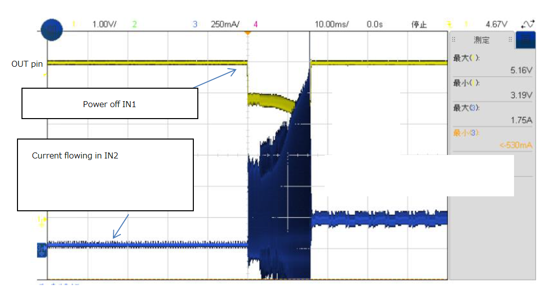
The attached figure below shows the behavior of the OUT pin when the voltage of IN1 is turned off with 5V applied to IN1 and IN2.
Immediately after turning off IN1, the OUT pin drops more than 1V.
The problem is that this state continues for about 7ms.
I checked the current flowing through IN2, but it cannot be said that the current detection is working.
The OUT pin voltage seems to oscillate during the 7ms period, so I suspect that the device is malfunctioning.
Please give me your opinion.

Best regards,

  • Hi Kaji,

    There is a possibility that the device is bouncing between the two inputs. Are you using any hysteresis in your design?

    What may happen during fast switchover is that when an input is loaded quickly, it's voltage drops slightly. This drop can then trigger another switchover event and the device gets "stuck" bouncing between the two inputs until one input is completely discharged.

    To get around this we recommend building a hysteresis window into the switchover voltage range. This means that the trigger points for switching from IN1 to IN2 and for switching from IN2 to IN1 are different. This is achieved by using a hysteresis ressistor to the ST pin. Please refer to Section 2.2.2 in this report to learn more about hysteresis.

    https://www.ti.com/lit/ug/tidue50/tidue50.pdf 

    If you have further questions, please also include your schematic diagram as this will help us provide better feedback.

    Thank you for using TI PowerMUXes in your designs.