This thread has been locked.

If you have a related question, please click the "Ask a related question" button in the top right corner. The newly created question will be automatically linked to this question.

BQ25886EVM: Default bq25886EVM could not be high current with no battery

Guru 19655 points
Part Number: BQ25886EVM
Other Parts Discussed in Thread: BQ25886

The condition of default bq25886EVM and no battery connection (and no thermister: only 10kΩ), system current could only up to 350mA.

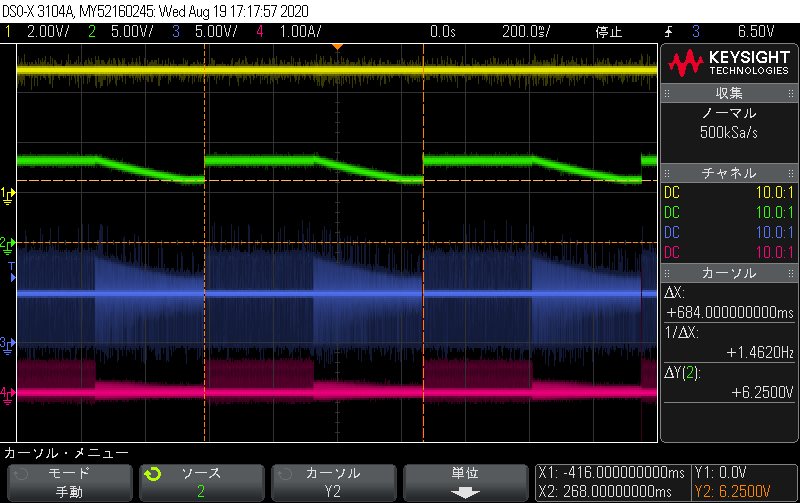
When system current over than 360mA, maybe occur current limit and Vbat decrease, waveform is attached below.

When bq25886EVM use on high current condition, is there changes point from bq25886EVM default setting?

Or, is 350mA limitation normal operation on no battery condition? 

※ch1: VSYS, ch2: VBAT, ch3: VSW, ch4: ISYS

Best regards,

Satoshi

  • Satoshi-san,

    What is the input current limit? This will be set by lowest of the ICO, ILIM, and D+/D- detection schemes.

    Thanks,

    Ricardo

  • Ricardo-san

    Thank you for reply,

    ILIM is about 2.9A and RILIM: 383Ω on EVM default setting.

    Please let me know if there any concern points.

    Best regards,

    Satoshi

  • Satoshi-san,

    Could you describe your D+/D- connection? Also what is the current limit on your supply?

    Thanks,

    Ricardo

  • Recardo-san

    About D+/D-, when JP3 and JP6 set two pattern: left short and open, results was the same.

    (Host USB is not connecting) 

    Input DC supply is 5A current limiting, I think that enough large.

    Best regards,

    Satoshi

  • Satoshi-san,

    With D+/D- shorted, what does VBUS and IVBUS look like upon POR? This will roughly capture the ICO value set.

    Also please capture VBUS (at the chip) and IVBUS when ISYS goes greater than 350 mA.

    Thanks,

    Ricardo

  • Ricardo-san

    Thank you for advice.

    I will capture you advised for next week.

    Please wait for little while longer.

    Best regards,

    Satoshi

  • Ricardo-san

    I update information, please see below;

    When I changed only JP12: open and JP16: 8.2Vset from EVM default value, Isys became 420mA_max and maybe Iin clamped 455mA.

    I captured Vbus (Yellow), Vsys (Green), Vsw (Blue), and IVBUS (Pink), please see attached below.

    ①Isys: 0A

     Phenomenon: Unstable and STAT pin blinking 1Hz 

    ②Isys: 50mA ~ 200mA

     Phenomenon: Unstable and STAT pin blinking 1Hz, and occur strange noise 

    ③Isys: 270mA

     Phenomenon: Stable and STAT pin: High, IVBUS clamped 455mA and VSYS decrease 7.8V

    ④Isys: 350mA

     Phenomenon: Stable and STAT pin: High, IVBUS clamped 455mA and VSYS decrease 6.0V

    ⑤Isys: 470mA

     Phenomenon: Nearly 100% Duty operate, IVBUS is roughly same as ISYS, VSYS decrease 4.5V

    ⑥Isys: 550mA

     Phenomenon: Nearly 100% Duty operate, IVBUS is roughly same as ISYS, VSYS decrease 4.0V

    ⑦Isys: 720mA

     Phenomenon: Could not capture because Electric load occur reverse current protection

    Please let me know if there anything points and advice.  

    Best regards,

    Satoshi

  • Satoshi-san,

    Just to clarify, you are observing these phenomenon with D+ and D- shorted together?

    Thanks,

    Ricardo

  • Ricardo-san

    Yes, D+ and D- are left shorted.

    By the way, I measured on D+ and D- (= JP3 and JP6) left open, results was the same.

    Best regards,

    Satoshi

  • Satoshi-san,

    This is very unusual. Is you electronic load active upon POR or do you let the device power up and then apply the load? Additionally are you operating your electronic load in CC or CR mode?

    Thanks,

    Ricardo

  • Ricardo-san

    I apologize for delayed my response.

    Electronic load is active upon POR, and I used CC mode.

    I tried power up and then apply the load, results was the same.

    I mistaken D+ and D- connect short. When D+ and D- connect "correctly" short, Iout is increase and input current became nearly 1A.

    Maybe last question, the same condition with no battery changed to JP1 connect 2~3 pin (connected LDO_in and VBAT).

    On the startup occur large inrush and VBUS decrease less than 4.3V, it is abnormal operation.

    (EVM Continue to operate ON/OFF)

     Please let me know if there any measure.

    Or, is these connection not recommend?

    Best regards,

    Satoshi

  • Satoshi-san,

    I do not recommend having the electronic load active upon POR. Wait for steady state and then apply the load.

    You will want D+ connected to D-. 

    This is not abnormal operation. The BQ25886 cannot reduce the system current load, so if the input power is not sufficient to power the output the device will crash. 

    There still seems to be a limit on your input current.

    You could be in VINDPM, what is VBUS at the IC? If you increase VBUS, does the input current increase?

    The ICO may be reducing the input current. Reduce your input cable impedance as much as possible.

    Thanks,

    Ricardo

  • Ricardo-san

    Thank you for advice,

    I re-measured correct Load and D+/D- condition, please see update below;

    ・Input current is set enough, DC supply set 5A_max and clamped about 1A by D+/D- setting.

    ・VBUS is based on 5V.

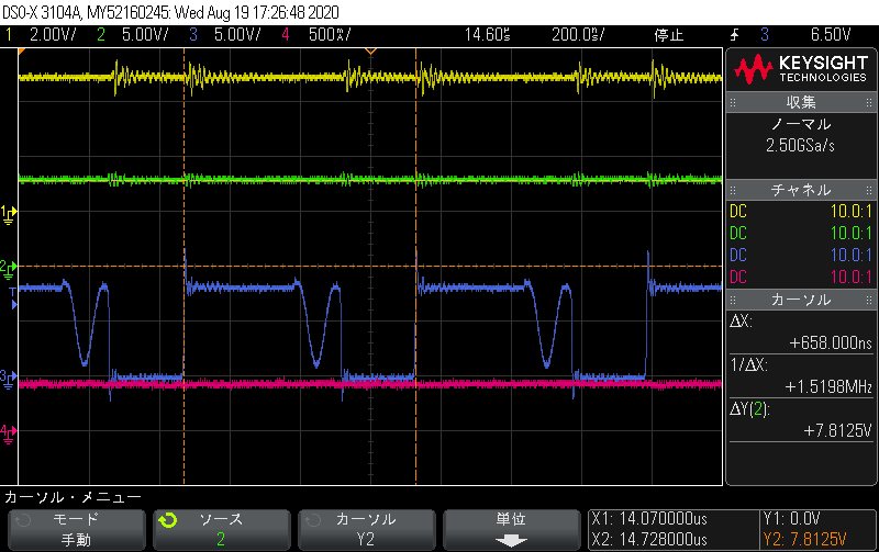
    ・When VBUS increase to 6V, problem waveform is attached below.

     VBUS increase or ISYS decrease have a tendency to occur below waveform.

     For example, border are 5.3VBUS and 590mA_ISYS, 5.6VBUS and 640mA_ISYS, 6.0VBUS and 700mA_ISYS

    ch1 (Yellow: VBUS), ch2 (Green: VSYS), ch3 (Blue: VSW), ch4 (Pink: Iin)

    Best regards,

    Satoshi

  • Satoshi-san,

    Shorting D+ to D- will set your current limit to 3A.

    Thanks,

    Ricardo