This thread has been locked.

If you have a related question, please click the "Ask a related question" button in the top right corner. The newly created question will be automatically linked to this question.

TPS92520-Q1: Inquiry

Part Number: TPS92520-Q1

Hi team,

I have some questions of TPS92520-Q1 from customers.

1. Is there any detecting system of LED circuit open?(There is no register bit for open circuit) How much the period of checking register bit for short/open fault detecting

2. Sampling time of monitoring LED voltage.

- Customer set 100% of PWM duty when LED is turned on. At that point, the voltage that is monitored may be the value of 18us ago?

3.Does the register of Limp home setting write down on non-volatile memory?

- If so, how many times it can be written on the memory?

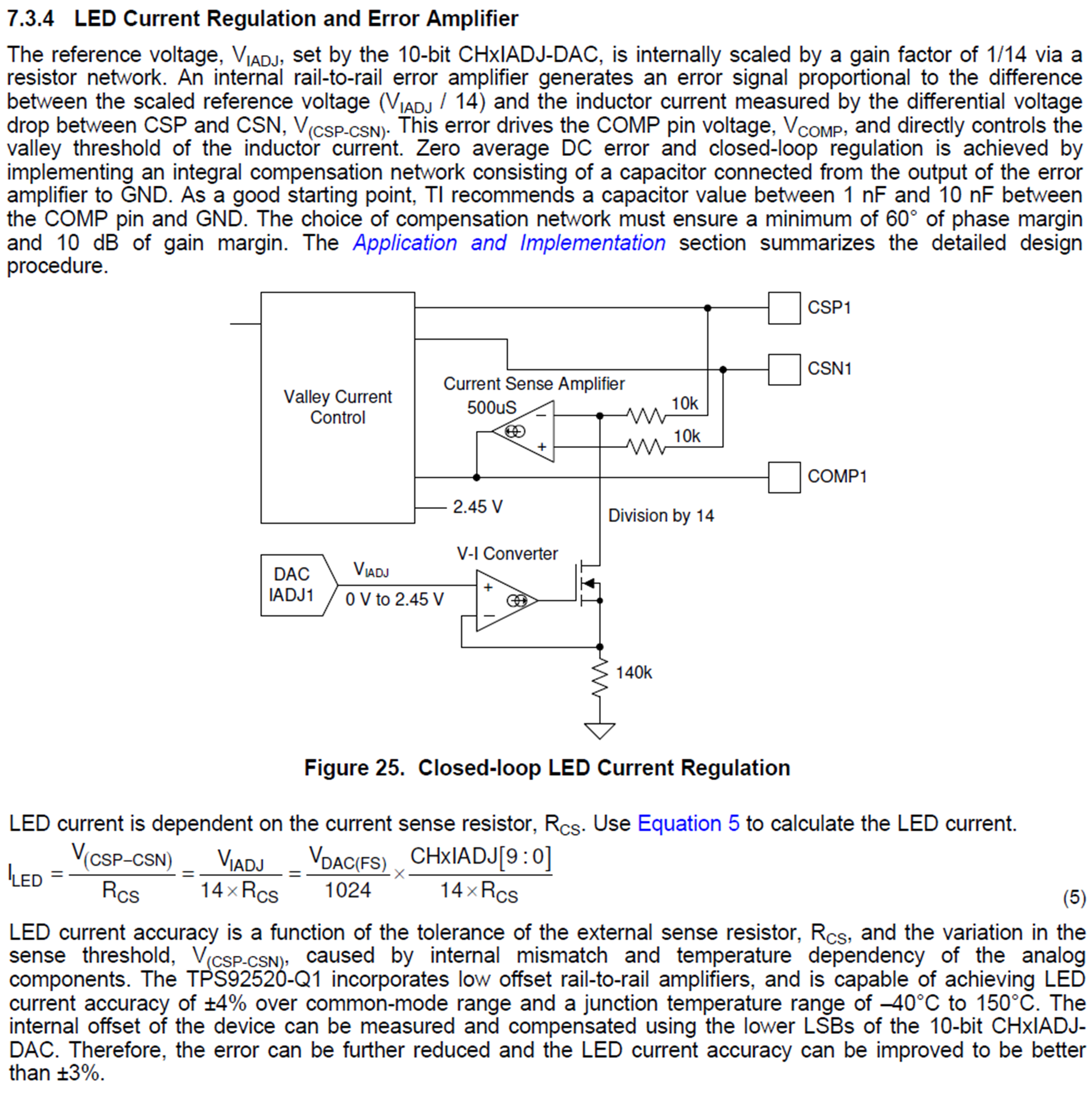
4. When setting the value of current using register of IADJ, is there any equation of calculating the current?(Or just using Hex value?)

5. If the value of LED voltage is monitored, can we calculate the value of Hex as the below equation?

- (65/255) × CH1VLED = LED voltage

6. How can we adjust switching frequency of BUCK?

7. Is there any function for supporting EMC reduction?

8. Could you give me some example code of IC driver?

Thank you for your support in advance.

Best Regards,

Kevin Shin

  • Hello Kevin,

    1. There are several ways to detect if there is an open circuit.  All of this is covered in the datasheet in section 7.3.15. Let me know if you don’t understand this section.
    2. The output/LED voltage (CHxVLED registers) are sampled by a round robin method where the sampling period is 18us, but it has to sample all the other outputs before it resamples the output/LED voltage input (CHxVLED) again. This is covered in section 7.3.12 of the datasheet. That will be on the order of 810 us (45 inputs by 18us).  
    3. The Limp Home registers are volatile. If 5VD is removed then the registers will be set to their default values, including the Limp Home registers. Their micro should be setup to program limp home registers at startup or after POR conditions.
    4. The LED current is set by a few things and is covered in the datasheet in section 7.3.4 and section 8.

    5.  I suppose you could estimate it, but why would you want to do that?

    6.  The CHxTON registers (address 0x11h and 0x12h) sets the frequency for each channel. See section 7.3.2 of the datasheet. On how to calculate it.

    7.  There is no “function” like dithering in the TPS92520 that can be used for EMC reduction. Good components select, layout, and design can ensure passing of EMC requirements.

    8.  I will have to look into that and get back to you.  

    Let me know if you have any other questions.   Most of this is covered in the datasheet.  Please review it and let me know if there is something that isn't clear.  

    -fhoude

  • Hello Kevin,

    I have sent a friend request with my email address.  Email me and I will send you a preliminary app note with code examples.  

    -fhoude