This thread has been locked.

If you have a related question, please click the "Ask a related question" button in the top right corner. The newly created question will be automatically linked to this question.

TPS543B20: TPS543B20 remote sense issue

Part Number: TPS543B20

Hi all, 

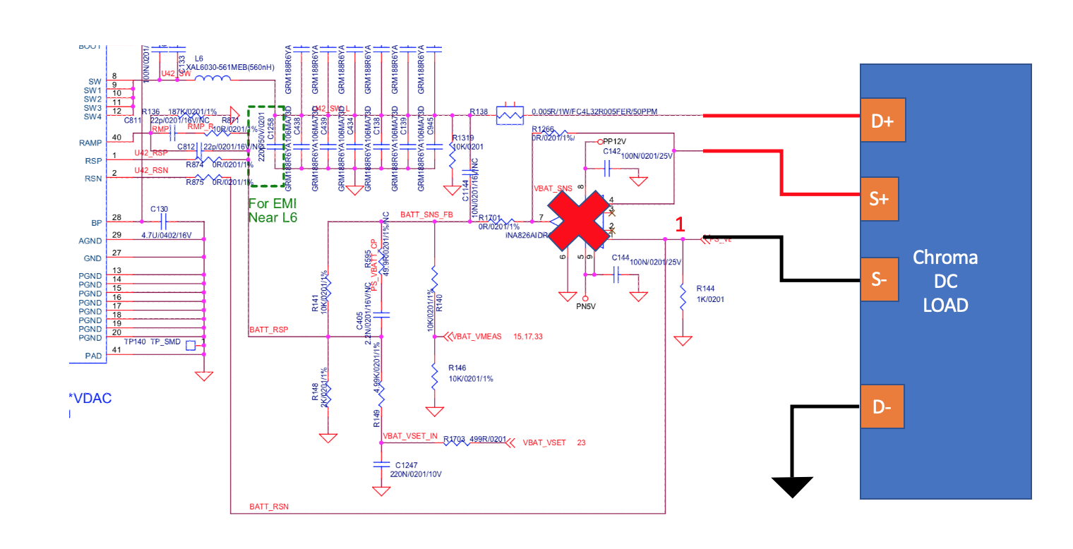
I'm using the remote sense control , but got some problem, schematic is in below (1)

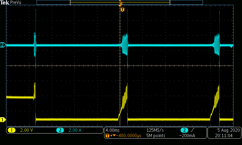
1. If i connect RSN pin directly (Mark 1 in schematic) to DC LOAD S-, seems keeping hiccups (2)

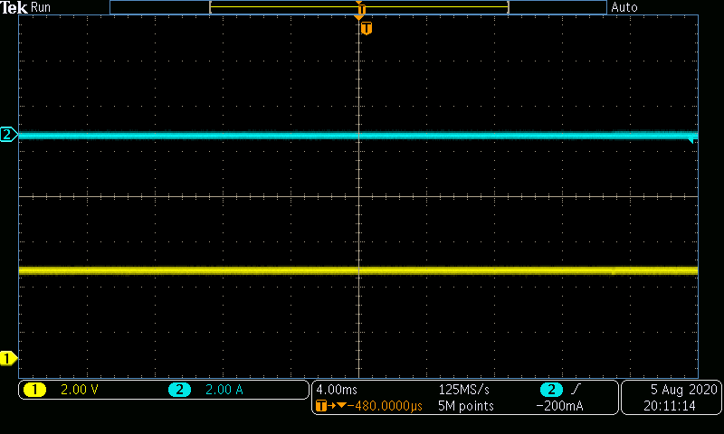
2. but if i connect RSN directly to GND, let it be local sense and it will be fine(3)

I'm wondering why it's happens and how it's fix. 

I set the voltage through "vbat_vset" net to let my output voltage adjustment.

Thanks, Frank.


      (1)

 (2)

 (3) 

  • Hi Frank,

    It looks like you may be tripping the OVP (described in datasheet Section 8.4.14)

    Where is your board ground connected to the eload ground (D-)?

    With the RSN connected to board local ground, can you please measure the potential difference between the board local ground and the D- on your eload?

    Regards,
    Kris

  • Hi Kris, 

    For the Question 1 ,

    • BUCL IC GND will directly connect to board ground.
    • E-load ground(D-) will go through a 0ohm and connect to board ground.

    For the Question 2 ,

    • If RSN connected to board local ground, it's almost zero voltage between the board local ground and the D- on eload.
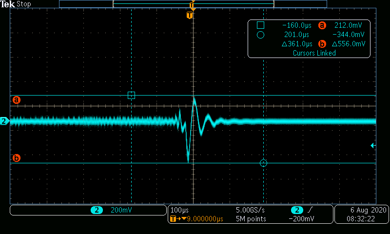
    • If RSN connected to remote side, eload D-, will cause hiccups like the wave below.(measure between local ground and RSN)

    if there is anything i can do, please let me know

    Thanks.

    Frank.

  • Hi Frank,

       Is this noise on ground happening every switching cycle?

    Regards,

    Gerold

  • Hi Gerold,

    I think it's not noise, this should be affect by hiccups.

    only appears when hiccups occur .

    thanks.

    Frank.

  • Frank,

    Looking at your hiccuping waveform in your first post, it looks like the output is initially fine before it then rises up and the part goes into hiccup. Can you share the waveform of what is happening prior to the part starting to hiccup? Is there any system event such as some circuit turning on, or load current being applied, that occurs at this point, after which you start seeing the output hiccup?

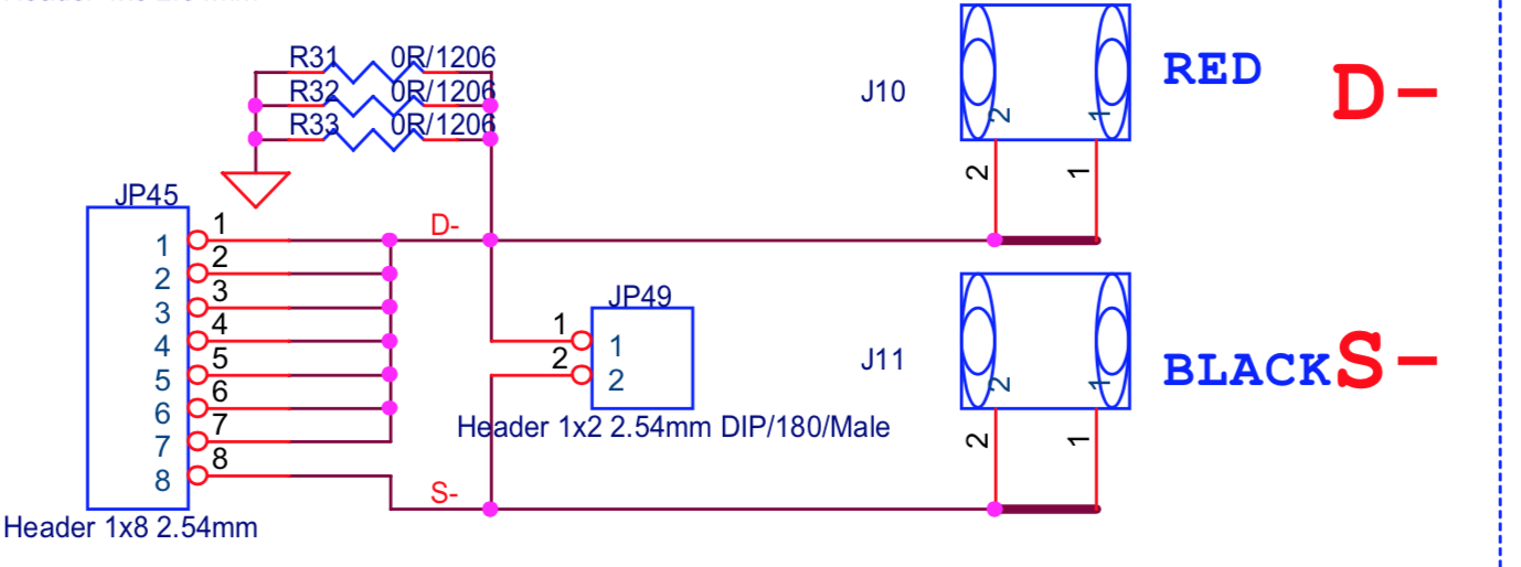
    I do not quite understand what the new schematic snippet is showing relative to the initial schematic you shared. How does this connector fit in with your first schematic showing the TPS543B20?

    Can you please help me understand by drawing them together? And can you please note how the schematic and connector and eload are connected for the two configurations you describe in your first post (1) connect RSN pin directly to S- and (2) connect RSN directly to GND? What is S- on eload connected to in case (2)?

    Regards,
    Kris

  • Hi Frank,

        Can you please get back to Kris' question in the above post?

    Regards,

    Gerold

  • Frank,

    The Sense pins (S+ and S-) on a load are not low-impedance outputs that provide the voltage applied to the load, they are high-impedance inputs that are connected to the sourcing supply's output so that the load can compensate for the drop across the wires from sourcing supply to the load.  While they may have some internal connection to D+ and D-, it will be high impedance to prevent the sense leads from carrying current into the load, but there may be no connection at all.

    Rather than trying to use the S+ and S- connections of the load for the remote sense, I would recommend:

    1) Configure the load for Remote Sense of its input voltage

    This is how the load is intended to use the S+ and S- connections, and the S+ and S- connections of the electronic load are connected to the power-out terminal of the power supply and the RSP and RSN terminal connections are also connected to the power output terminals of the power supply.

    The load will now compensate for the drop across the power leads connecting it to the power supply and report the voltage at the power output terminals.

    2) Configure the Power Supply for Remote Sense and Load for local sense

    Connect the power output terminals of the power supply to the D+ and D- terminals of the electronic load

    Connect the Remote Sense terminals of the power supply to the D+ and D- terminals of the electronic load to sense the voltage applied to the load.

    Connect the S+ and S- terminals of the load to the Power D+ and D- terminals of the electronic load so that the load reports the voltage at the D+ and D- terminals.

    If you are using configuration #2, it is possible that there is too much propagation delay from the output of the TPS543B20 through the load connections wires, to the load, and the TPS543B20's control loop is operating too fast to stabilize the input to the load.  If that is the case, you will need to change R1701 (VOS input node) from 0-ohms to 100-ohms and populate C1144 a capacitor to cancel the delay through the power path leads to the remote sense point.

    The exact capacitance needed will depend on how much inductance there is in the power path, I would recommend starting with a 100nF capacitor, which will give you a 16kHz cross-over frequency with a 100-ohm resistor.  You can decrease the capacitor value to increase the bandwidth of the remote sense path once the circuit is working.