Other Parts Discussed in Thread: BQSTUDIO, GPCCHEM, GPCCEDV
Hi all, we are now starting production for our device which uses the bq27220 fuel gauge. On our initial run, we are seeing inaccurate battery percentages after loading the same FlashStream file (that has previously worked on our prototypes) to the bq27220. Digging into this some more, I think that the fuel gauge is not going through enough charge/discharge cycles in order for it to "learn" the parameters of the FlashStream file.
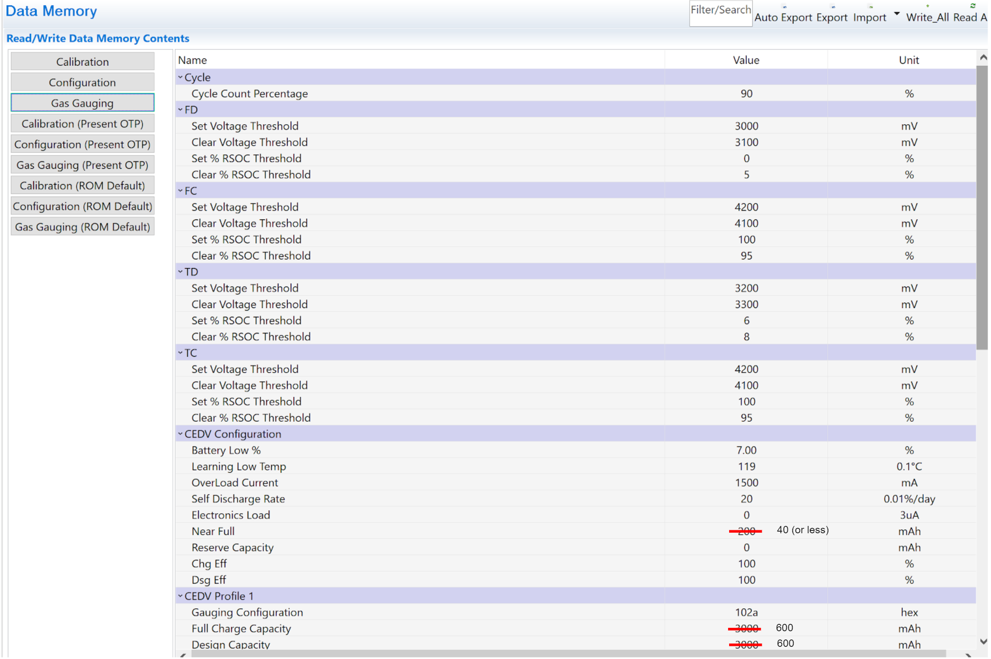
Looking at the following screenshot from the part's TRM:

1. If FCC only reduces by 256mAh at most per update cycle, does that mean that for our application, where we are going from the default 3000mAh to our battery's 600mAh, it will take us over 9 charge/discharge update cycles before the fuel gauge is ready to go? It doesn't seem like a viable option to ship these devices to consumers and ask them to not take the reported battery percentage into account for a few weeks...
2. What is the recommended procedure to be performed on the production line for devices using the bq27220, so that they are ready-to-ship with accurate battery percentage reporting?
3. What is the standard check to know when the fuel gauge has completed its 'learning'?
4. Is there a way to load the battery characterization onto the fuel gauge such that no 'learning' needs to happen? If yes, what would this characterization process look like? It seems like there would be some way to put all fuel gauges into the same initial state since we have the full profile of the battery we will be using.
Would really appreciate some prompt input here so we can move forward with shipping these devices to our customer.
Thanks in advance,
Vignesh