This thread has been locked.

If you have a related question, please click the "Ask a related question" button in the top right corner. The newly created question will be automatically linked to this question.

UCC28251: Secondary side control - Rcs calculation

Part Number: UCC28251

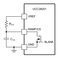
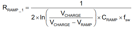
For a half bridge controller with the UC28251 in secondary side control and I am not clear as to the calculation for Rcs for the CS pin for secondary side control. Could you please guide me to the correct formula or document?

Also if possible, I'd like some idea on how to calculate the Cz and Rz for EA- & COMP damping as well. 

  • Hi,

    The datasheet has a secondary side design example which shows how to sense the current. Basically a current transformer and an opto are required.

    For feedback loop design, you can follow typical type II or type III compensation design which can be found in books or on line. For on line, you can search type II or type III loop compensation you will see steps.

  • I am talking about the Ramp pin driven from the V_ref pin in secondary mode control. 

    Sorry for the confusion.

    The compensation part is clear thanks. :)

  • Hi,

    You can still use the same equations but replace Vin with Vref.

    Vramp, Equation (29), let Vin/(2n) = Vref

    Then in equation (34), replace Vcharge with Vref

    Cramp still needs an arbitrary pick up, say 470pF.  

  • I will thanks. But I am not clear about the Vpre-bias and Vsr_ramp calculations in eq29.

    My reference voltage is 1.74V at the EA+ pin

  • Vsr_ramp = 3V is a fixed number.

    Vpre-bias is the voltage at your converter output after power on, when SR control starts. For secondary side control, as Vin/(2n) is replaced with Vref, Vpre-bias should be just set up with 3V. 

  • what is your further question?

  • The issue is as below:-

    Vref=3.3

    Vpre_bias= 3

    Vsr_ramp=3


    Vramp  = Vref – Vprebias      x Vsr_ramp         = ( 3.3 – 3 ) x 3 = 0.3 / 2 = 0.15

                       2 x Vprebias                                                        2 x 3


    Vramp=0.15 V


    Considering C = 100pF (as in SLUU441A)

    Vcharge = Vref = 3.3

    Fsw = 200kHz

    Rcs = 1 / [   2 x ln{ Vcharge / (Vcharge – Vramp)} x Cramp x Fsw ]

    Rcs = 1 / [ 2 x ln( 3.3 / 3.15) x ( 100 x 1e-12 ) x (200 x 1e3) ]

    Rcs = 1 / (1.86 x 1e-6) = 537403 Ohms = 537 KOhms


    Where as in SLUU441A Rcs is 100K or 10K i am not sure


  • R29 can be found in the user's guide from BoM, it is 10k.

    So the design did not pick up Vpre-bias = 3V, and should be < 3V. I do not know exactly what Vpre-bias picked up for that design. But if you pick up 3V, then you can just use the calculation results you obtained. If you want to match that design, you need to pick up a different number.

    Actually you can use equation (29) as is, and plug your Vin, n, to determine Vramp. After you estimate Vramp, you will get a corresponding Rramp.

    You even can make a Vramp arbitrary. The critical thing here is Rramp. After Rramp is calculated, the Vramp is actually backwards achieved.

  • I back-calculated and got Vpre as 1.09V for C=100pF and R=10k

    The thing is that I normally like to know why I am using the components as well :) 

    Thanks for your support. If you can show some more light on this in the future I will greatly appreciate it.

  • I think you can back calculate equation (29) as is, i.e., with your Vin and n, and with Vpre-bias = 3V.

    As it looks to me your design has no pre-bias, so the calculation for your design has more options. But if your design does have a pre-bias, equation (29) should be used as is.