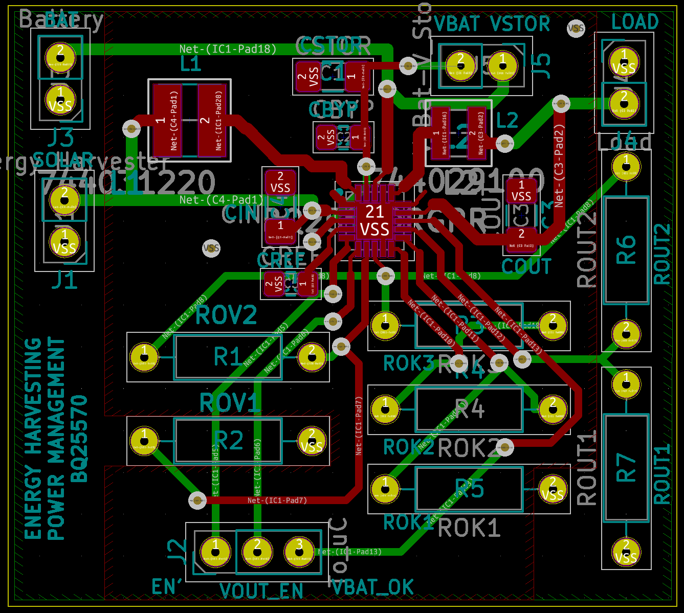
Taking the answers you provided, I designed a PCB with the BQ25570, which you can find here: https://www.dropbox.com/s/4lwgx6h46k4pvoo/BQ25570%20interface.rar?dl=0
Unfortunately, the circuit is not working as expected. To be specific, when I connect the PCB with a small solar cell I use, VStor (and after CHgen, Vbat as well) start charging, but they never reach the supposed overvoltage level (4.2V). What actually happens is that charging stops at around 3 Volts and then the behaviour of the circuit is undetermined and not the expected, with voltage levels fluctuating around random values that change every once in a while (for example, it may drop down to 2 volts, or increase to 3.3 volts and stay there for some time).
What I would like is, if possible, to take a look at the PCB design (pcb kicad file, provided in the link above) to point out any potential errors, as well as to check the values in the component list I have placed below, in order to find out the potential cause of the problem.
- Capacitors
- Cin 4.7uF - X7R
- Cstor 4.7uF - X7R
- Cbyp 0.1uF - Z5U
- Cout 22uF - X5R
- Cref 10nF - X7R
- Resistors
- Rout1 = 3.16MΩ
- Rout2 = 10MΩ
- Rov1 = 5.1ΜΩ
- Rov2 = 6.8MΩ
- Rok1 = 5.1MΩ
- Rok2 = 6.49MΩ
- Rok3 = 1.3MΩ
The expected voltage levels are as a result: Vout =5.039V, Vbat_ov = 4.235V, Vbat_ok,hyst = 3.0582V, Vbat_ok,prog = 2.74978V
- Inductors
- L1 (Lboost) is wurth elektronik 744031220 - 22uH
- L2 (Lbuck) is wurth elektronik 744029100 - 10uH
- Storage element
Simple Electrolytic capacitor 6600uF, 6.3V
Let me know if I can provide any more information that might be useful to debug my problem.
EDIT: I am attaching photos of the schematic and the PCB, if kicad files do not work for someone:
Schematic

PCB: