This thread has been locked.

If you have a related question, please click the "Ask a related question" button in the top right corner. The newly created question will be automatically linked to this question.

LM5069: Current Limiting in Battery + Inverter/Charger scenario

Part Number: LM5069
Other Parts Discussed in Thread: LM5066, TPS1663

Dear everyone,

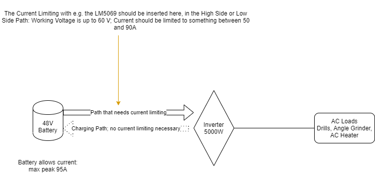
I have an LM5069 and want to use it for Current Limiting. My setup is an 48V LiIon battery on an inverter. And I want to limit the currents that flow in operation through power tools as drills on the DC side, so between Battery and Inverter. And in my prototype transients pass through unlimited. Since my battery shuts off at an overcurrent event of 95A, it then shuts off. So, I wonder if the LM5069 circuit is fast enough and suitable for my application


The continuous load dont trouble the battery, the short transients during startup of the AC loads are the problem, cause they reach up to 150A in the DC side for a couple of milliseconds (Waveform attached) - measured across a 200A/60mV shunt

.

The inverter/charger has an input capacitor of around 3mF. But charging that input capacitor didnt cause any problems so far.

And for the first prototype it is not so necessary, that the circuit must also allow for a charging of the battery through the inverter, so current in the opposite direction. But if anyone knows a solution that also accounts for that, it would be even better.

I dimensioned the LM5069 circuitry using the excel tool, my schematic looks like this:

In my understanding this circuit should limit the current as soon as the voltage between Vsense and Vin is over 55mV. Or is that only working once at startup conditions?

Any help would be highly appreciated.

  • Hi Hugen,

    Welcome to E2E

    Hot-swap controllers LM5069, LM5066 are pretty fast in breaking the path for excessive overloads. For higher current applications, I would recommend LM5066 as it has lower sense voltage which would minimize power loss across sense resistor.

    The body diode of the external FET provides path to charge the battery from the inverter side. As long as FETs are ON, the current will flow through the FETs and does not harm the body diode/FET.

    Can you fill in the design calculator and send me for review. 

    Best Regards, 

    Rakesh

  • Hi Rakesh,

    thanks for the reply and the recommendation for the other IC, which is way better for the reduced conducting losses as you stated.

    I attached the filled calculator for the LM5066.

    So as it seems it must have been a manufacturing problem in the last prototype rather than a problem with the general behaviour and the concept itself should work out?

    Kind regards,

    Hugo

    LM5066 Design_Calculator_REV_B - filled.xlsx

  • Hi Hugo,

    You can use latest MOSFET for better SOA margin https://assets.nexperia.com/documents/data-sheet/PSMN2R3-100SSE.pdf

    Please find the attached updated design sheet. The design looks good to proceed with PSMN2R3-100SSE

    modified_LM5066 Design_Calculator_REV_B - filled.xlsx

    Best Regards, Rakesh

  • Thank you for the suggestion Rakesh.

    Unfortunatly the PSMN2R3-100SSE has a quite bad availability. If i proceed with the PSMN4R8-100BSE the SOA margin results to 1.12 if I enable the dv/dt control. Do you think that would still be in an accetable range?

    And do you have any idea, why my last setup was not working? Could it be that these type of soft start circuits only work at the first power up and not when the output voltage reached the nominal voltage, as it is in my case. (Since I need the current to be limited during normal operation when the inverter already is booted and AC loads drain these high transients)

    Kind regards,

    Hugo

  • Hi Hugo,

    SOA margin >1.1 is acceptable. Enable dv/dt control and proceed with the PSMN4R8-100BSE

    These devices does active current limiting or power limiting (which ever is lower) during startup and acts like a circuit breaker (allows transient overload current for fault timeout period without active current limiting. Please refer Section 8.3.2 Circuit Breaker in the LM5069 datasheet.

    Best Regards, Rakesh

  • You're answering speed is really great, thank you a lot for that!

    Ah, then I understand why my last solution did not work. Then it seems that hotswap controllers are the wrong device for our usecase, I think we talked at cross purposes.. Do you have any idea how I can limit current after startup/during normal operation (for example for around 100ms before it latches off)? Does TI offer any product for that?


  • Hi Hugo,

    You would need current limiting device like TPS1663 but unfortunately, we don't have solution for your current level.

    Best Regards, Rakesh

  • somehow it says here, that current limiting is always enabled. But it says that too for the LM5049, which I already unsucessfully tried.. Leaves some confusion.

  • Hi Hugo,

    Extremely sorry for the confusion.I will check with the team on the product selection table.

    Best Regards, Rakesh

  • Hi Hugo,

    In general, most of the hot-swap controllers does circuit breaker operation for overload (not current limiting) because current limiting causes lot of power stress on the hot-swap FET and is difficult to manage.

    Do you have any follow-up questions ? please let me know.

    Best Regards, Rakesh

  • Hi Rakesh,

    thanks for the reply. So there are some hot-swap controllers that do current limiting before circuit breaking? Could you name any?

    Kind regards,

    Hugo

  • Hi Hugo,

    All our controllers are circuit breaker type. Unfortunately, I am not aware of devices which does current limiting at such power level.

    Best Regards, Rakesh