This thread has been locked.

If you have a related question, please click the "Ask a related question" button in the top right corner. The newly created question will be automatically linked to this question.

BQ76200: Separate discharge/Charge path solution consult

Part Number: BQ76200
Other Parts Discussed in Thread: BQ76920, BQ76940, BQ76930, , BQ76952, BQ76942, BQSTUDIO

Hi team,

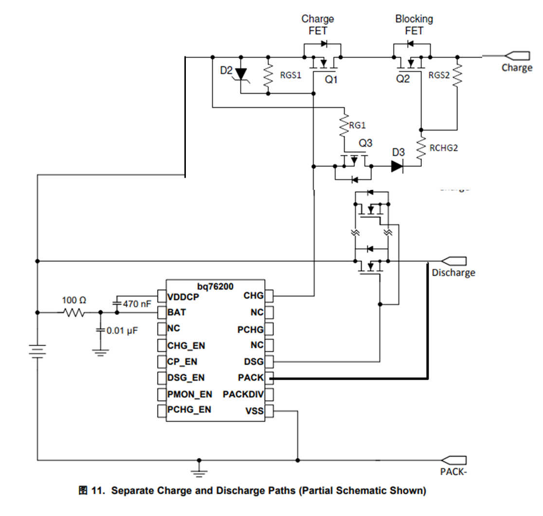
My customer wants to separate the discharge/Charge path in the 50V/60A BMS system, I want to recommend the customer use the below solution. Could you please help check if this solution can work?

If not, do you have other solutions that can be penetrated here? Thanks.

BR,

Charles Lin

  • Hi Charles,

    Yes, this solution can work. This document has multiple examples with this device: https://www.ti.com/lit/an/slva729a/slva729a.pdf

    The BQ76200 is designed as a companion device for the BQ76920 (up to 5S), BQ76930 (up to 10S), or BQ76940 (up to 15S). 

    We also have new family of battery monitors that can support separate charge and discharge paths - the BQ76942 and BQ76952 and these devices have the high-side FET drivers integrated. There is a new video series recently released that introduces these devices:

     Video 1: Introduction to the BQ76942 / BQ76952  https://training.ti.com/node/1147222

    Video 2: BQ76942 / BQ76952 device overview https://training.ti.com/node/1147223

    Video 3: Evaluation module and Battery Management Studio (BQStudio) software configuration https://training.ti.com/node/1147224

    Video 4: FET configurations and cell balancing https://training.ti.com/node/1147225

    Best regards,

    Matt

  • Hi Matt,

    Thank you for your information here. I have one more question here,

    -Since PACK connects to the discharge path and no connection to the Charge path, how can CHG signal turn on Q3 here? I think the source of the Q3 is floating and CHG cannot turn on it. Am I right? Thanks.

    BR, 

    Charles Lin

  • Hi Charles,

    Q3 is a P-channel FET.  The gate of Q3 is held at the battery+ voltage which is the BAT pin voltage at DC.  When CHG goes high the source of Q3 goes above the gate and Q3 is on. With Q3 on D3 is on and Q2 is on.

    Turn off can be slow for Q2 since when Q3 is off it is RGS2 which turns off Q2.  You would like to select FETs so Q3 has a lower Vgsth than Q1 and Q2. 

  • Hi Matt and team,

    Sorry about my mistake. I mean the source of Q2 is floating, when Q3 is on, how can CHG signal turn on Q2? Thanks. 

    BR,

    Charles Lin

  • Hi Charles,

    If CHG is low (at the BAT potential) Q1 and Q3 are off, Q2 is free to float to any potential based on leakages or influence of the CHARGE terminal. RCP2 will hold the Q2 source and gate at the same potential.

    If CHG is high (above the BAT potential, see V(CHGFETON) in the data sheet), Q1 is on, so the drain of Q2 is held at the BAT potential.  The body diode of Q2 will prevent the source from going more than a diode drop above the drain.  Q3 is also on which pulls up the gate of Q2, so Q2 is on.