A related question is a question created from another question. When the related question is created, it will be automatically linked to the original question.
If you have a related question, please click the "Ask a related question" button in the top right corner. The newly created question will be automatically linked to this question.
TPS25942L: Priority Power Multiplexing Implementation
I understand that you are implementing Priority Power Mux operation and not paralleling.
If there is a OVP or OCP event on U27, this efuse (U27) will turn OFF and the output goes to 0V.
This means that OVP of U28 is pulled low which turns the U28 efuse ON. Now, it depends on the PSU2 and Load if an OVP or OCP event also happens on U28 and turns it OFF.
U27 FLT and PGOOD are both MOSFET grounded, change to FLT to operate normally,
1. When U27 OVP, U28 OVP is connected to U27 PGOOD, the output is no voltage (PGOOD still has 1V voltage)
2. When U27 OVP, U28 OVP is connected to U27 FLT, the output is U28 output
3.U27 =>MAIN PSU / U28=> BACKUP PSU
If U28 OVP is changed to U27 FLT, when the voltage of U27 is less than the voltage of U28, the output will be fixed by U28 and cannot be switched back to the main power supply of U27, unless U28 fails or the voltage is less than U27
PG1 still has 1V voltage when PSU1 OVP (the OVP of a single U27 is tested, the normal PG1 is 0V, as long as U28 is powered on, PG1 will have 1V) resulting in U28 also no output
Yes, you are right. If it is an OVP condition on U27 and not a UVLO condition, the PGOOD will still be high and U27 will turn OFF itself as well as U28.
In this case the FLT/ will help in turning ON U28 when U27 has OVP.
1.PG1 is the open drain pull low, where does 1v come from?
2.Because when U28 is not powered on, U27 has OVP. At this time, PG1 is 0v ......
2. If U28 OVP is changed to U27 FLT, when the voltage of U27 is less than the voltage of U28, the output will be fixed by U28 and cannot be switched back to the main power supply of U27, unless U28 fails or the voltage is less than U27
When you say 'PGTH connect to VIN' , does that mean PGTH of U27 is connected to VIN of U27 (DCIN_12_M) ?
Is PG of U27 connected to OVP of U28 or you are using
Are you sharing waveforms with circuit tested in the below configuration ? If not, can you share the schematic for each condition that you have shared waveform for ?
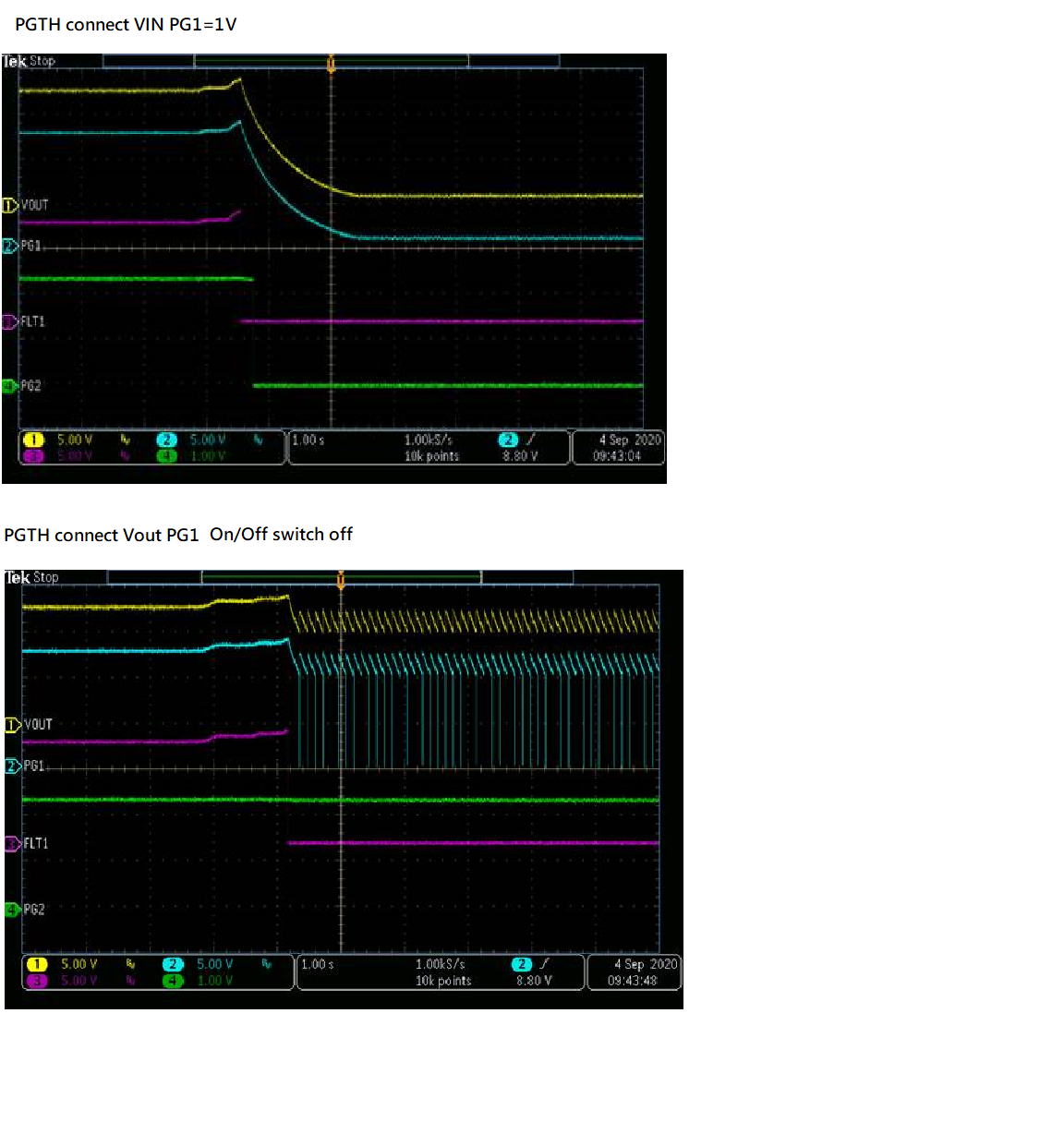
The root cause of the problem is that the PGOOD signal is not pulled low by the controller when there is an OVP event.
The PGOOD continues to be high and reflect the Pullup voltage (Vout1). So, initially when there is an OVP event, the output keeps discharging anf the PGOOD also follows output as PGOOD is pulled upto Vout. Once the PGOOD-1/OVP-2 reaches less than ~1V, the Channel-2 turns ON and the OUTPUT starts to ramp up. When Vout ramps up, the PGOOD-1 and OVP-2 also ramp up there by turning OFF channel-2. This continues in a cycling process and the VOUT oscillates.
The Priority Muxing configuration mentioned in datasheet is not recommended for input OVP conditions.
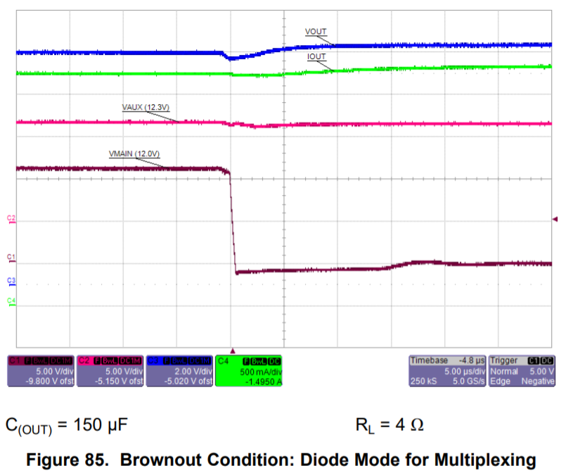
When the primary power supply is present and within limits the primary channel should supply power irrespective of whether it is higher or lower than the secondary power supply. Please refer to waveform captures from datasheet below.
Please verify the connections on your board and try replacing the IC with new IC and re test
A-The connection method of waveform captures (Figure 80~83) is PG1 to OVP2 in the datasheet
But when it is changed to FLT1 to connect to OVP2 ,When the voltage of U27 is less than the voltage of U28, the output will be fixed by U28 and cannot be switched back to the main power supply of U27, unless U28 fails or the voltage is less than U27
B- When PG1 is connected to DMODE2, it takes a very long time (300ms) for VOUT to switch to PSU2 after PSU1 is turned off.
Will it not be (400uS) when changing to FLT1 and DMODE2? But does DATASHEET indicate the need to connect PG1 to DMODE2?
When Vout is greater than Vin1, the FLT/ is asserted due to reverse voltage and this will turn ON Ch-2. Similarly, CH-2 will be OFF only when it sees reverse voltage that is Vout > Vin2.
In Condition 2 when PG1 is connected to DMODE2 the transition should be very fast as shown below. The below waveform is captured with Cout = 150uF and Rload = 4 ohms. What is your Cout and Rload ? Can you restest with Cout = 150uF and Rload = 4 ohms ?