This thread has been locked.

If you have a related question, please click the "Ask a related question" button in the top right corner. The newly created question will be automatically linked to this question.

TPS54331: Schematic/layout review for tps54331

Part Number: TPS54331

Hi team,

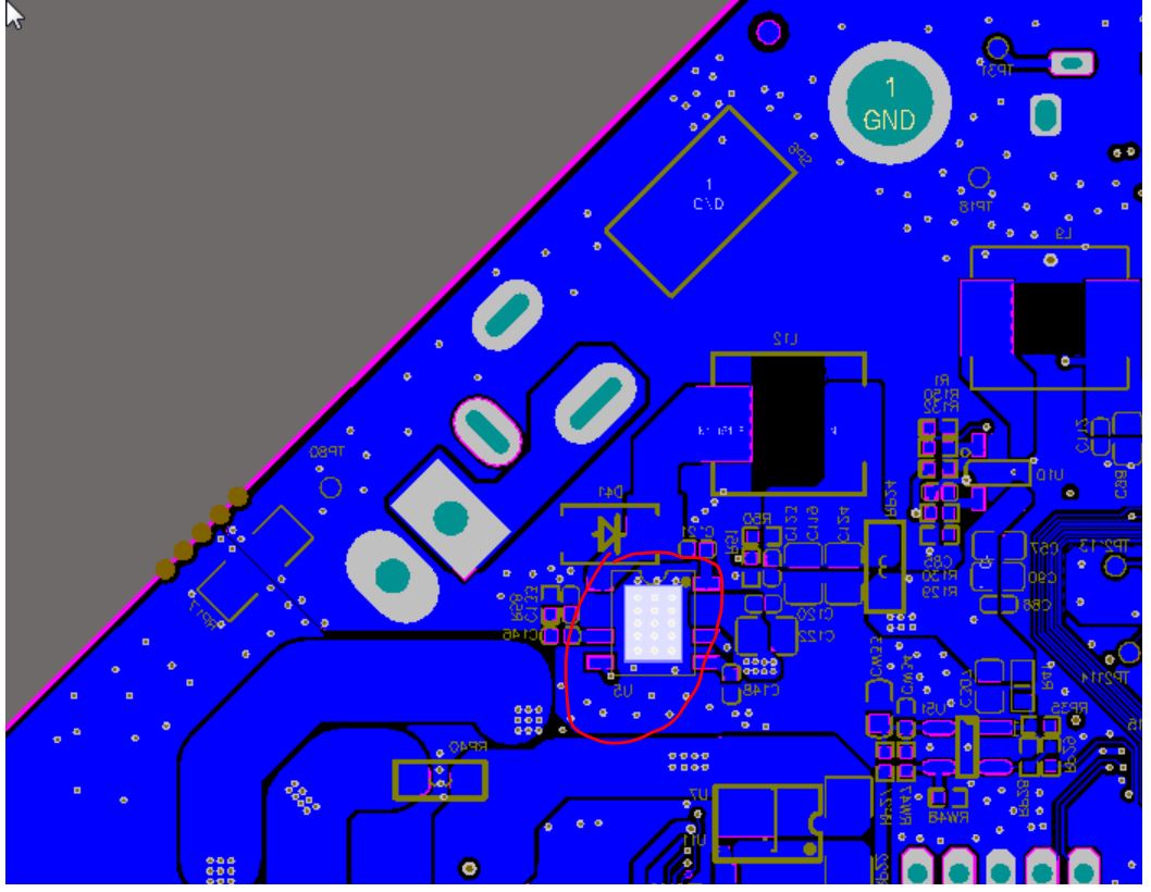
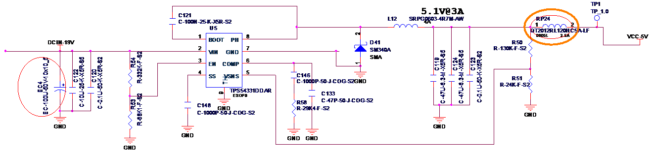
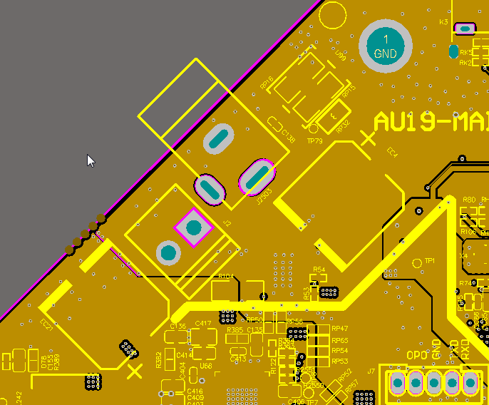
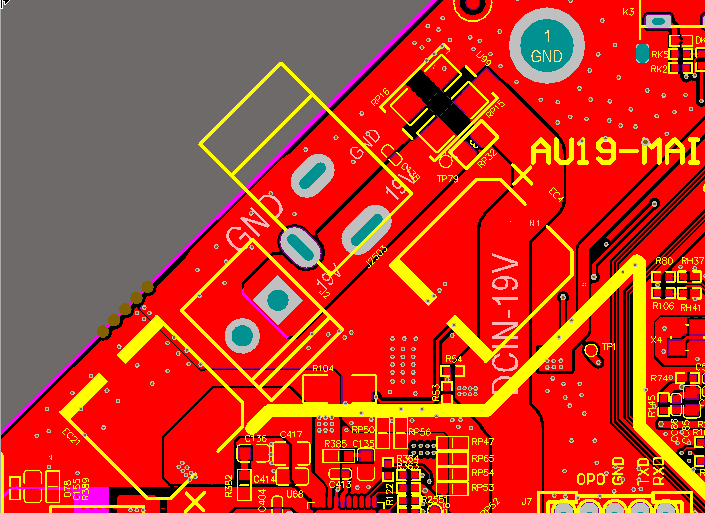
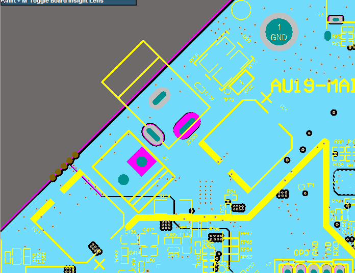
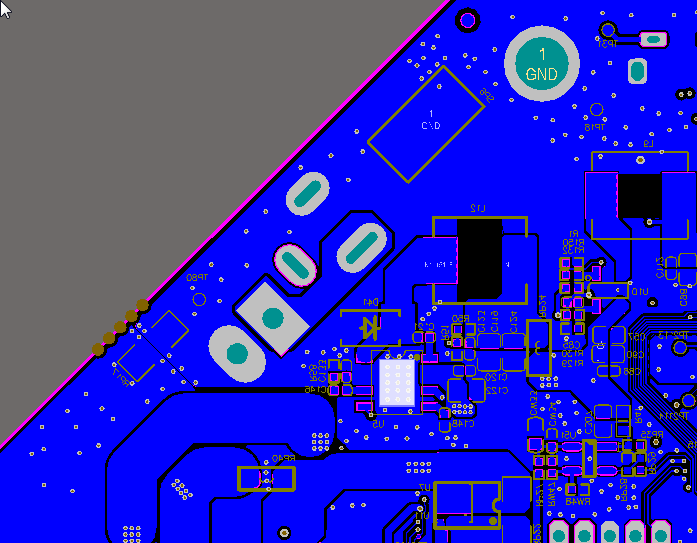
My customer would like to have your help to review schematic/layout as below figure.

Any suggestion will be welcome. Thank for your help.

  • Hello, 

    I will review the SCH and the Layout, can you please confirm the following: 

    • the indurctor value, nit very clear from the SCH
    • VIN=19V,
    • VOUT=5V
    • and IOUT=3A. 
    • can you please circle where is U5 in the layout you provided. 

    Thanks 

    Tahar 

  • Hi Tahar,

    Thank for your help.

    Yes. I confirm the spec :

    Vin=19v

    Vout=5v

    Iout=3A

    L=4.7u 4A

    Also please refer the layout of U5 which is located at bottom layer.

  • Hi Tahar,

    Thank for your help.

    Yes. I confirm the spec :

    Vin=19v

    Vout=5v

    Iout=3A

    L=4.7u 4A

    Also please refer the layout of U5 which is located at bottom layer.

  • Hi Feng Bin,

    Here are my SCH comments:

    • Adjust the LC filter, increase the inductor to 8.2uH. 2x47uF is good
    • CBOOT needed to 100nF, I cannot read clearly the value in your SCH.
    • The Feedback resistor values does not see right to give 5.0V out. it is set to 4.23 instead, please use equation 05 in the datasheet, the VREF is 0.8V. OR use 10.2K and 1.96K, it should give you 5Vout.
    • What is the desired Soft start? With 1000pF, the SS time is 0.4ms.
    • The EN is good, with VIN=19, VEN is 3V. just keep in mind the max VEN is 6V.

    Layout comment:

    • The PH trace needs to be as small as possible. The inductor pushed too far out and created a long PH trace, that is not recommended as it creates noise in the board.
    • Add ore VIA on the VIN trace to help thermal dissipation

    Thanks

    Tahar