Hey!
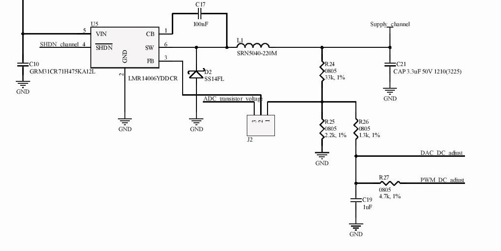
I'm implemeting design mentioned in the article https://www.ti.com/lit/an/slyt777/slyt777.pdf?ts=1597909097823 (Fig.10) with LMR14006 converter.
DC output of the converter is set by PWM fed to FB pin through resistors. DC voltage value is fine and matches the calculations.
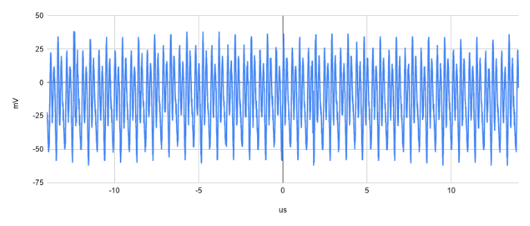
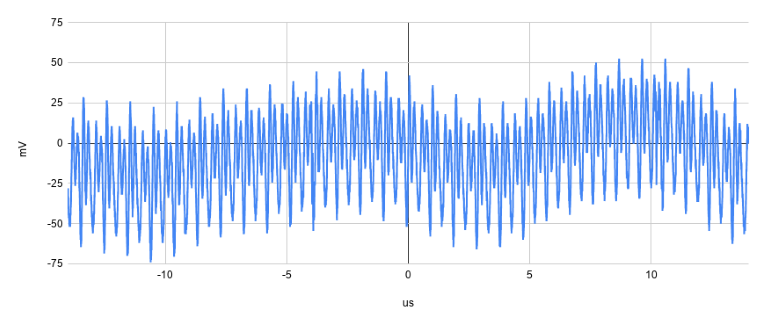
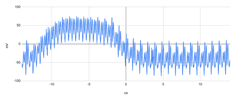
However I'm not happy with DC waveform measured with oscilloscope. I attached few expamples with different voltage outputs (signlas AC coupled for better view). I can see 2.1 MHz pulses whick is fine and sometimes some other disturbances which is no good.
Is there general technique to keep DC value clean without disturbances with multiple voltage output values?
My input is 24V and output should vary from 5V to 20V with loads roughly 100 - 300 mA.
Thanks!


