This thread has been locked.

If you have a related question, please click the "Ask a related question" button in the top right corner. The newly created question will be automatically linked to this question.

TPS2121: Possible SS Capacitor pop while using the IC on no load and no switch over.

Part Number: TPS2121
Other Parts Discussed in Thread: TVS1800

We are using TPS2121 to switch over from 9V mains to battery boosted voltage 9V. We are using TI Samples for our prototype board.

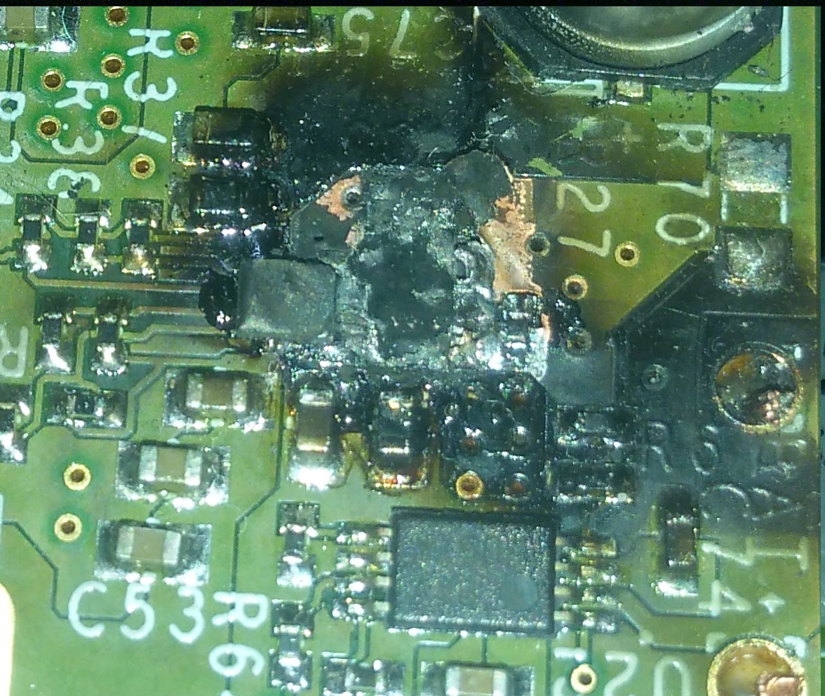
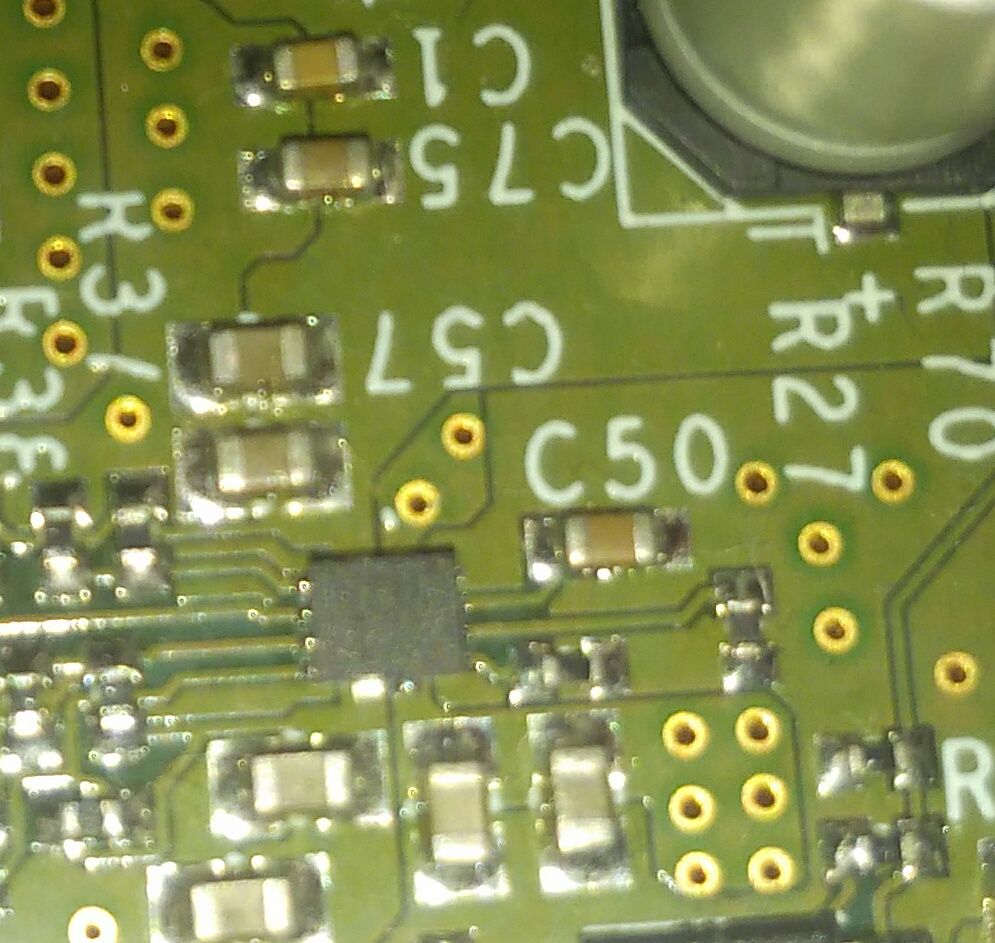
The SS capacitor section of our board randomly burned today. The load was not connected. TPS2121 had only second source (IN2) from the battery boosted regulator output. 43K & 5.1K are the protection resistors used. We are not sure if the TPS2121 burned of if it was the SS capacitor. The section of TPS2121 with SS pin is damaged and the SS capacitor area seems to have popped and the traces are damaged.

We have a 12V version of the same PCB design running without issues though. It has different switch over and OV resistors. Other TPS2121 components remain the same.

Thanks in advance.

  • Hi Jomon,

    Without a schematic or waveforms it is not possible to figure out if the TPS2121 was damaged or if the damage is limited to the SS cap.

    The SS pin is not a power intensive pin and is only used when during the soft start and switchover states. Is it possible to further test this TPS2121 unit?

    If possible, It would be good to view VIN, VOUT, ST and IOUT as the device soft starts into 9V.

  • The IC is burned and then there are no issues on other boards which use the same IC. All other boards are working fine.

    The switch over of this IC was proper when it was alive, and when the burning happened, there was no switch over, but it was working only on IN2 with IN1 disconnected. The board is completely burned with no traces left in the area. TPS2121 is only partly damaged, but the PCB section with the SS capacitor seems bulged when looked from the other side.

    The boards were into production as there were no issues even at 2A load, and it has been running for a few days until today when it accidentally started to burn with no load connected. Just wanted to check for the cases that results in the popping of SS or TPS2121 burn, and to stop the production if needed. IN1 has a TVS1800 for plugin surge protection as recommended.

  • Hi Jomon,

    The failure mode where the SS cap fails is not something that is expected. Usually, it will be the power path that had high potential to fail thermally.

    There could be an external path to the SS pin which shorted higher voltage onto it causing damage. What is the SS cap rated for? Another option is that the internal gate voltage was imparted directly onto the SS pin and the cap was not rated for it. On the TPS2121 EVM, we use 50V rated SS caps.

    It is difficult to pinpoint the source of damage as we do not have waveforms that describe that failure and since you mention that the device is implemented and working on other boards. 

  • Thank you for the reply.

    We too believe that the common point of failure should be on the power path.

    We read that the SS pin has a recommended maximum voltage of 4V, and thus had used a 25V capacitor. Since the maximum voltage in the circuit is 9V, should a short from those voltages to the capacitor, if any, will it not still be OK for the capacitor and within its rated voltage ?

    What would happen if the capacitor was short circuited and the TPS2121 had a 0R effective on its SS pin ?

    Regards,
    John

  • Hey John,

    With a 0Ohm resistance from SS to GND, the device will not turn on. The SS cap adds a capacitive delay to the gate drive circuitry which allows for the linear turn on. If this pin is shorted to GND, the gate will not be charged as there is a low resistance path to gnd.

    During normal operation the SS max is only 4V so a 25V cap here should be acceptable. The gate voltage will be much higher than 9V to turn on the FET but I doubt that the gate voltage was directly imparted on the SS pin.

    Is it possible to turn on the device at all?

  • The shown image is the condition of the IC. The IC on the left of the burned area is the TPS2121. The burned area had SS capacitor. The image of the similar are on another PCB is shown below.

    Regards,
    Jomon

  • Hi Jomon,

    The damage is a lot more intensive than I imagined. 

    Is is possible to perform the exact same test/setup that was place on this board before and share the waveforms? If you would like, feel free to share them with me directly at s-dmello@ti.com along with a circuit schematic.

  • We were not actually performing anything on the board. It was just left without any load.

    Will share the waveforms on the board in your email to continue this further.

    Thank you so much!