This thread has been locked.

If you have a related question, please click the "Ask a related question" button in the top right corner. The newly created question will be automatically linked to this question.

LMG1210: none encryted PSPICE (SNOM677.ZIP) model does not work in LTspice?

Part Number: LMG1210
Other Parts Discussed in Thread: TINA-TI

Team,

Has this problem already been reported? Is it expected?
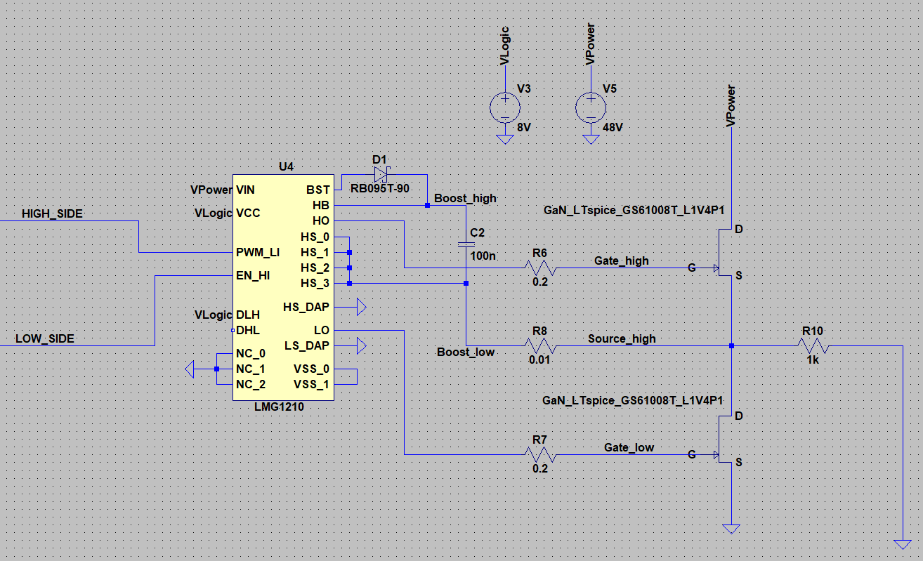
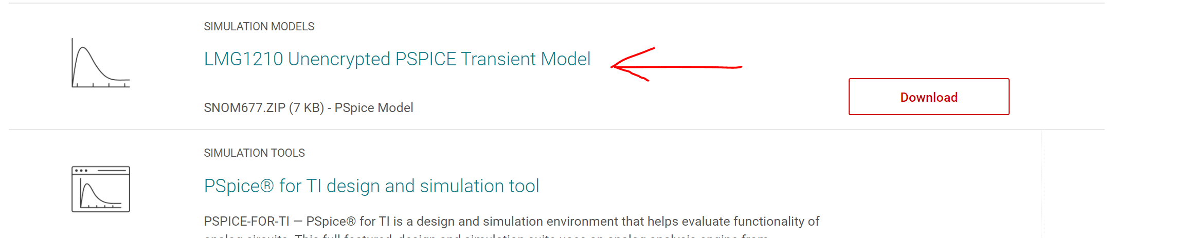
Can this the LMG1210 model SNOM677.ZIP be used with LTpsice?

Customer can not use TI version of PSPICE as their IT security policy does not allow for online installer (and we do not have any off-line TI version of PSIPCE)..

Thanks in advance!

A.

  • Hello AnBer,

    Thanks for reaching out.

    I am not aware of this "issue". Is customer trying to import the model and running into issues or are they able to import the model then running simulation to encounter simulation error? If so, what is the error message?

    Regards,

    -Mamadou 

  • Hello Mamadou,

    I am the customer with the LTSpice LMG1210 problem. I build up a test circuit like the reference circuit from TINA TI in LTSpice (see attached image).

    The transient simulation result is also attached. It can be seen that although the switching signals are applied at the LMG1210 I do not get any output to the high side switch. Only a few, strange looking pulses can be observed at the low side output.

    Do you have any suggestions what the problem might be?

    And can you maybe tell me why the Spice model has so many different pins than the real IC?

    These are the Pins according to the Spice lib

    HB
    HO
    PWM_LI
    HS_0         -> in the IC are only 3 HS Pins. Why are 4 in the model?
    HS_1
    HS_2
    HS_3
    HS_DAP    -> no correspondence in datasheet
    LS_DAP     -> no correspondence in datasheet
    VIN
    LO
    DHL
    DLH  
    VCC
    VSS_0
    VSS_1        -> is this the same as VSS_0? In which case do you not connected this to VSS_0?
    EN_HI
    NC_0
    NC_1
    NC_2           -> why is there a third NC? The IC only has NC and NC_1.
    BST

  • Hello Christian,

    Thanks for the details.

    Allow me to look into this before suggesting possible root causes.

    Expect to hear from before COB Friday.

    Regards,

    -Mamadou

  • Hello Christian,

    Thanks for your patience.

    Can you please confirm that you're using the unencrypted version shown below?

    I have reviewed the simulation schematic and from the looks of it, VSS_0 and VSS_1 are floating whereas these pins should always be the GND reference point. Can you please update schematic with decoupling capacitor on VCC pin similar to TINA-TI reference design? Let's also remove R8 and short HS pins to High-side source. Please re-run simulation to check whether this addresses the issue.

    Regards,

    -Mamadou

  • Hi Mamadou,

    thanks for the reply. Seems as if my problem was that simple that I only forgot the GND connection. Thanks, but I haven't seen that. Now the model is running without problems.

    Best

    Christian