This thread has been locked.

If you have a related question, please click the "Ask a related question" button in the top right corner. The newly created question will be automatically linked to this question.

UC3843: Feedback Question and How to Debug

Part Number: UC3843
Other Parts Discussed in Thread: TL431, UC3842, LM2596

Hi Everyone,

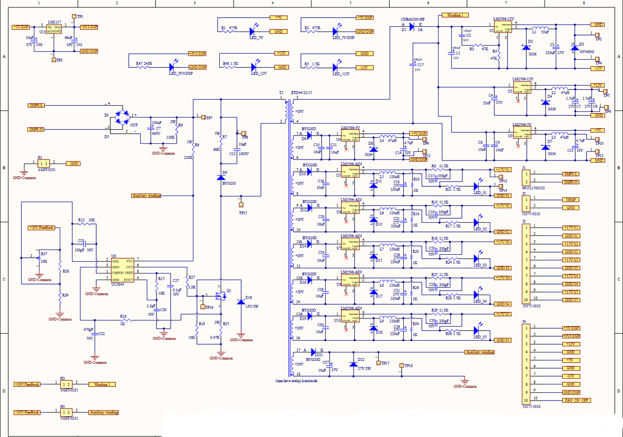
We are using UC3843 to get AC/DC Auxiliary Power Supply. Please Find Schematics below.

Regarding to below schematic, is there any problem? For the feedback pin which header (H2 or H3) should I use?

Since it is a high voltage AC circuit, how can I start to run circuit step by step? Do you have any suggestion?

  • Hi Mert! 

    Thanks for getting in touch with us and for using the UC3843 in your design!

    A major issue I see here is that you do not have any isolation between your first secondary winding and the feedback of the IC. This could lead to damaging the controller. Adding isolation in these types of designs is often done with a TL431 and an opto-coupler, one good example of TL431/opto feedback can be found in Section 9.2 of the UCC28C4X datasheet. The component choices and design process are discussed in detail there. 

    Some other things to check: 

    • Make sure your resistors (R6 and R9) are properly rated for the high voltage you're applying
    • R37 being a trim potentiometer opens the potential for shorting the output to ground, consider adding a resistor in series to prevent this
    • Make sure that C37 is sized to keep the VCC of the IC steady and above the UVLO threshold

    I suggest using H2 for feedback and not H3. Since only one output rail is being regulated it is generally best practice that the highest load rail is regulated. 

    As for getting started, begin by isolating the IC VCC pin and powering it using a benchtop DC supply and verifying the PWM output. After that, apply your VAC-in using a variac (starting around 20VAC) and check that the FETs are switching and you can see a current waveform on the sense resistor. Slowly raise the VAC using the variac and make sure to keep checking for unusual overheating/sounds/smells!

    Thanks again for reaching out, I hope this information gives you a solid starting point! 

    Aidan Davidson

  • Hi Mert!

    To add on to my initial reply:

    My recommendations for using H2 for feedback instead of H3 and adding the TL431 and opto for isolated feedback were made based on the assumption that Winding 1 is the line with the highest loading (based on the 3 output rails coming off). I also assumed that you are looking for an isolated supply based on the different ground notations between the primary and secondary side. H3 and the AUX winding could be used for feedback without any additional components but if the AUX winding is not the highest loaded it may negatively affect the other output rails. 

    It may be better to use the UC3842 instead of the UC3843 here. We generally recommend the UC3843 for DC/DC converters with dedicated VCC supplies whereas the UC3842 has a much wider gap between UVLO on and UVLO off that makes it better suited to off-line power supplies where the VCC may vary more.

    Another good place to get started would be supplying the device's VCC with a benchtop DC supply. As you slowly ramp up the DC voltage, you can see the device begin switching and check everything is operating properly. You can also use a variac to slowly ramp up your AC voltage

    What are your input/output specifications here? (VinAC, Pout total, Pout per rail, isolated/non-isolated)

    Please see the links here for some great design resources:

    Thanks again for getting in touch, I hope this helps! 

  • Hi Aidan,

    Thanks for your support. Your isolation comment true if we use H2 for feedback as you suggested. What about using H3 for feedback for this prototype? It will be hard to add optocoupler to PCB.

    I have double checked R6 and R9 resistors. They are high watt and ok for the calculations.

    I will add series resistor to R37 in order to prevent short circuit thanks.

    I will check again the value of C37 to get a steady voltage, thanks.

    Thanks for the starting point I will try DC equivalent voltage to test IC. Do you have any advice how to tweak compensation network?

  • Hi again Aidan,

    While I work on the reply I could not see your last message sorry.

    Actually design is not belong to me, there is a working prototype with some pcb and cables shown below. There is not any schematics :( Then I am trying to understand circuit and run my new circuit. When I looked datasheet I saw UC3842 will be better option, but parts were bought. Maybe I will purchase UC3842 for the final, thanks. Task is totally catastrophic, first I would like to make circuit run, then for the future projects I will ask for the right application choice for our input/output specifications.

    I think I will use H3 header and rely on regulation of LM2596 :( 

    I will remind VCC DC supply and ramp up advices thanks. For the second phase of running, do you have any advice how to tweak compensation network?

  • Hi Mert! 

    A good resource for getting started with feedback & compensation is Section 9.2.2.10 of the UC3843 datasheet. I hope your next version of the supply comes together nicely (and more well-documented than the first)!

    Thanks again for getting in touch Mert, I hope all this info helps! 

    Aidan

  • Hi Aidan,

    I have started work on this circut again. Regarding to your suggestions I have a question.

    Aidan: Another good place to get started would be supplying the device's VCC with a benchtop DC supply. As you slowly ramp up the DC voltage, you can see the device begin switching and check everything is operating properly. You can also use a variac to slowly ramp up your AC voltage

    Mert: I supplied VCC from benchtop DC supply and ramp up DC voltage. When DC voltage above 8.4V it began switching but after 1-2 seconds stopped switching. Then I turn off and turn on supply, then again it begins switching but after 1-2 seconds stops switching. Is it normal? By the way When PWM stops switching, there is 5V at VREF.

  • Hi Aidan,

    The reason is current flowing through RSense, since R6 is not isolated properly for the test to supply standalone VCC. Thanks