This thread has been locked.

If you have a related question, please click the "Ask a related question" button in the top right corner. The newly created question will be automatically linked to this question.

TPS2543: design that used to work with 2540 now doesn't work...

Part Number: TPS2543
Other Parts Discussed in Thread: TPS2540

I have a design that used the TPS2540. Now due to availability I ordered a batch of PCBs with the TPS2543 which was supposed to be pin compatible. 

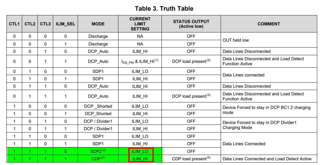
In my design I need only one current limit. So I hardwired the ILIMSEL signal to GND and hooked up the limit-setting resitor to ILIM0. 

In my design I need only one configuration: CDP / BC1.2. So I hardwired the CTL signals to 111 . 

So when testing the old boards, I hook up a tablet and it can communicate with the host, in this case an FT312D chip. And the tablet starts charging at 1.45A. Good. 

But the TPS2543 boards just consume 0.013A total (the FTDI chip) and no communication happens. Is this expected behaviour for the TPS2543?

  • Hi Roger,

    The TPS2543 has an extremely small supply current, in the range of uA. Where are you measuring the 0.013A current at? 

  • I'm powering the board from a lab power supply that shows me the current draw. So if you say the TPS draws on the order of uA, it is entirely possible that the whole board draws 13mA: 13mA for the FTDI + 5uA for the TPS reads on the powersupply as 13mA. 

  • Correct. If your power supply is powering your entire system and it says that the total system current is 13mA, it is not the TPS2543 drawing all of that current. Here is a graph showing the current draw of the TPS2543 depending on the power state

  • You are focussing on the wrong part of my posting. Your replies do not help at all.

    I tried the "live chat" to get an "instant answer" and was told to send an Email and to expect a resolution in/answer in 24h. We're now 24h short of "a week". 

    The TPS2543 is sold as a pin conpatible upgrade. I had 100 pcs soldered onto boards where i make a very small margin on selling those. 

    It  seems that the TPS2543 is NOT a pin compatible upgrade. It behaves different in my situation: ILIMSEL hardwired to GND and CTL hardwired to mode 7, DCP, the only mode I need. 

    I patched one board to wire ILIMSEL to "1". Now the tablet starts charging at 1A. This is odd, because I did not get around to connecting anything to ILIM1. So the resistance is "infinite" and so the charging currentlimit should be around <I don't remember, but less than 100mA> . 

  • kljadfjkladjklafljksd

  • What F*** stupid forum is this. I typed a whole reply  hit "reply" and... I get a "too small to read" red box in the corner and by the time I've arranged my glasses to be able to read that  it is gone. And so is the reply I've crafted. Great service. 

  • That is NOT helping. You're focusing on the wrong part. Great that the TPS is energy efficient, but that doesn't matter in my application. 

  • I contacted "live chat" and was told to send and EMail and expect an answer/resolution in 24h. So far we are now almost a week further with no help whatsoever. 

  • Hi Roger,

    I am happy to support you through the forums but please keep the conversation professional. I have been on personal leave which is why I have not been able to respond to your thread. 

    Would you be able to share a schematic of your design? I'm confused as to how you have the TPS2543 configured as in one post you state that it is configured for CDP with the CTL signals set to 111, while in another post you state that the CTL pins are hardwired to mode 7, DCP. 

    I recommend you double check your system in reference to the TPS2543 truth table. If you have the CTL signals programmed 111, and the ILIM_SEL pin is pulled to GND, the TPS2543 will actually reference the ILIM_LO resistor which seems you do not have. Since there is no resistor connected, the TPS2543 will effectively see this as a current limit of 0A, which is probably why there is no charge. 

    This also makes sense why if you change the ILIM_SEL pin to 1 it works. Once again looking at the truth table, when the TPS2543 CTL pins are 111 and the ILIM_SEL pin is also 1, the TPS2543 is in CDP mode and the TPS2543 uses the ILIM_HI resistor as reference. 

  • * I want to activate communication, I'm slightly dyslectic, so it is quite possible I misspelled/mistyped CDP as DCP. Sorry. (Annoying when a single (likely!) error results in another valid "codeword").  

    * I need only one current limit. No switching between the two. So hardwired the SEL signal to 0 and mounted the ILIM_LO limit-configuration-resistor. Why mount the other one when it will never be selected?

    * On one of the existing not-working boards I've been able to patch the select signal to high. With nothing on ILIM_HI, the "solder here" spot is too small for me to use. Can you explain that the current limit seems to be MUCH more than what I expect based on the datasheet? (infinite current-setting-resistor -> almost no current). 

    * That one board was destroyed by a colleague when explaining what to do for another project: "then after connecting <the other project>..." (not actuallly doing that) "...I hit this button" (actually doing it, providing 12V, max 5A to the board.....)

  • Hi Roger,

    When using the TPS2543, if you want to place the device in CDP mode, ILIM_SEL, CTL1,2,3 must all be pulled high to a value of 1. If you have CTL1,2,3 at a value of 1, and ILIM_SEL is pulled low to a value of 0, this puts the TPS2543 in SDP mode. You can reference the truth table in the TPS2543 datasheet for the pin strapping requirements for each mode. 

    Once you put the TPS2543 in CDP (CTL1,2,3 and ILIM_SEL = 1), you must have a resistor attached to the ILIM_HI pin in order for the device to be functional. If you have the TPS2543 in CDP mode, but no resistor on the ILIM_HI pin, this will cause the TPS2543 to have a 0A current limit, so the TPS2543 will never charge a connected device

  • So what you're saying is that it is not 

    > Drop-In Compatible with TPS2540/40A

    I remember seeing a much larger current limit than the "0A" that you say it should do. Any explanation for that?

  • No, based on my understanding of the two devices, it is not drop in compatible. Where did you see the claim that the TPS2543 is drop in capable with the TPS2540? Did an engineer here on the forums say this? Was this stated on either of the TI product pages for these devices?

    I can't comment on your test setup and the larger current limit you are seeing. All I know is that based on my experience with these devices, if you do not connect a resistor to one of the ILIM pins and then reference that pin with no resistor connected to it, the internal 5V power path will never be enabled. 

  • I found the "drop in compatible with TPS2540" in the datasheet. 


    To find it again I followed the link "TPS2543" in your post, then clicked on the datasheet. It is in section "1 features"

  • Hello,

    Thank you for the clarification. I will work with my team on getting this clarified.