This thread has been locked.

If you have a related question, please click the "Ask a related question" button in the top right corner. The newly created question will be automatically linked to this question.

TPS563201: Inductor value from WeBench and data sheet too low

Part Number: TPS563201

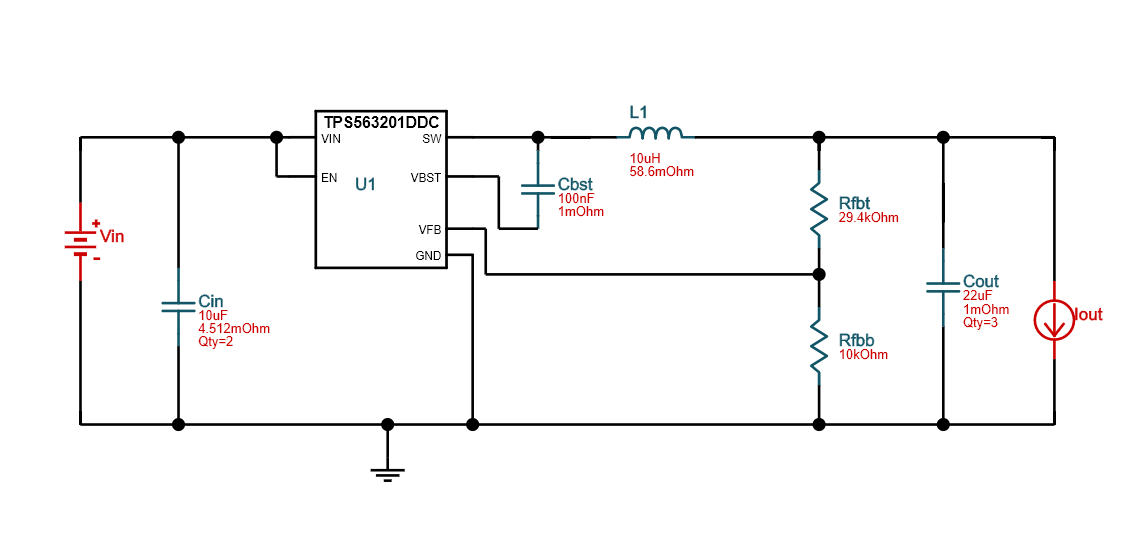
I'm designing a buck converter for a project I'm working on. I chose the TPS563201. I've put it all together on a breadboard. Input in 5v or 12v, the output is 3v. The WeBench tool says to use a 2.2 uH inductor. When I do, the output is not stable enough for my project. I tried a 6.8 uH and even higher, up to 68 uH inductor. The higher inductors seem to work and produce a stable output. The 6.8 is working fine, and I may end up using the 10 uh in the final project. The Data sheet says MAX inductor is 4.7 uH. What are the ramifications for using a higher uH inductor?

Here is a schematic:

  • Hi Edward,

    It looks like your schematic didn't upload correctly. Can you please try uploading again?

    Also - do you mean that you're evaluating the device performance using a solderless breadboard? A good PCB layout is critical for switching converters, and breadboards have a lot of parasitics that make them a poor choice for switching converter design. We recommend that you use a PCB and follow the datasheet recommendations for the layout. You can also upload your layout here to have it checked over before sending it off for fabrication.

    As far as using an inductor that's too high - it can negatively impact the stability of the control loop and the transient response of the converter. A higher inductance will also yield a higher DCR for a given package size.

  • Here is the schematic again, and PCB. I just copy pasted before. Here is an "upload" attempt. 

    I did follow the data sheet recommendations for PCB layout. I did get the PCB prototype ordered, so I can try with a smaller inductor and see how that goes. most of the smaller parts are being pick and placed onto the board, but I'll be putting on the inductor. In below PCB design, the TI chip is IC3.

  • Hi Edward,

    The layout looks good for me. I agreed to add 0.1uF ceramic cap at input side even WEBENCH haven't added it. 

    Have you tried 2.2uH inductor on your PCB board?  Frankly it doesn't make sense to me 68uH is stable while 2.2uH is not.

    Could you tell us the specific VIN/VOUT/IOUT condition of unstable point as well as the SW Node waveform? Thanks.