This thread has been locked.

If you have a related question, please click the "Ask a related question" button in the top right corner. The newly created question will be automatically linked to this question.

TPS1H100-Q1: Failure case

Part Number: TPS1H100-Q1
Other Parts Discussed in Thread: TPS4H160-Q1

Hi All,

I have aquestion about TPS1H100-Q1.

It's a difficult question, do you have the information and document below?

- Are there any events or cases where the IC burns or smokes?
- Also, please tell me the counter plans to take in that case.

Best Regards,
Ishiwata

  • Hello Ishiwata-san,

    If the application is designed correctly and the device falls within the recommended operating ranges as defined in the datasheet then the device will not have any chance of burning or smoking. The TPS1H100-Q1 is designed to be reliable and robust so that it can be designed into high reliability automotive applications. 

    That being said here are a few common design mistakes that could potentially result in the device having physical damage:

    • No reverse polarity protection. We typically either recommend a resistor/diode on the ground pin or upstream power protection such as an idea diode on the input power rail to protect against reverse polarity conditions (see 7.3.4.9 Reverse Current Protection in the datasheet). If there is no such protection and there is a reverse polarity event the absolute maximums of the device will be egregiously violated and could potentially result in damage to the device.
    • Inductive discharge above what the integrated VDS clamp is capable of discharging. If you have an inductive load on the output it will produce a negative voltage spike on the output when the load is switched off. The TPS1H100-Q1 has an integrated VDS clamp that will discharge the energy stored in the inductor, however if the inductor/current is large enough then the integrated clamp will not be able to discharge the energy and physical damage is possible. Refer to Figure 34. Maximum Current vs Inductance Range in the datasheet for the device's capabilities.
    • Any unprotected input transients not covered by the device. The TPS1H100-Q1 is certified for ISO7637-2 and ISO16750-2 transient pulse tests. It is also qualified for Device HBM ESD classification level H3A and Device CDM ESD classification level C4B. Anything above these transient conditions on the input without protection such as a TVS diode would violate the device specifications and potentially damage the device.
    • Hitting undervoltage lockout (UVLO) while in current limit mode. If the current limit is set too aggressively on the TPS1H100-Q1 and causes the upstream power supply to dip the input voltage below the undervoltage lockout voltage of  VS,UVF then the device's will attempt to shut off and the current will no longer be limited. This is often caused by the design not having sufficient capacitance on the input.

    Essentially the only reasons the device would physically burn or smoke are if it was being used in a way that it was not designed for or the absolute maximum values are being violated. If you are seeing damage in a specific use case please attach the relevant setup, schematics, and scope shots  so that we can narrow it down.

  • Hellow Timothy-san,


    Thank you for your reply and answer.
    I understand that the device will not break if used within the recommended operating range.

    I have additional questions.

    If the overload detection function does not work, thermal shutdown operates.
    Please tell me the maximum current value at before thermal shutdown operates.(Assuming overload detection not working)

    Or is there a waveform from overload detection to thermal shutdown? If there is, I want it.


    Best Regards,
    Ishiwata

  • Ishiwata-san,

    If the set external current limit is incorrectly configured or there is a break in the resistor connection to ground the device's internal current limit will be defaulted to. This is specified by Ilim,nom in the datasheet and for the TPS1H100-Q1 has a minimum of 7A and a maximum of 13A. This would be the max current limit that the device is possible of regulating to regardless of the state of the CL pin. If the internal and external current limit are not regulating then the device is not operating correctly and cannot be considered reliable. 

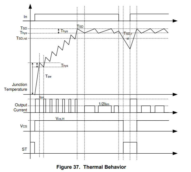
    One statement I wanted to correct you on is, "If the overload detection function does not work, thermal shutdown operates.". This is not entirely true. The current limit will regulate correctly to the set current limit and go into thermal shutdown if the device is functioning correctly. This is the case with having a short-to-ground scenario or setting the current limit too high and trying to charge a load capacitance that is too big. The current limit is hit, the TPS1H100-Q1 regulates to the set current limit, the junction temperature of the internal FET heats to the thermal shutdown temperature, and then the device shuts off. I would recommend referring to the driving loads application note (https://www.ti.com/lit/slvae30The behavior can be seen in the following figure from the TPS1H100-Q1 datasheet:

    Once the device cools to under the thermal shutdown reset temperature the device will retry with a 50% current limit set. I don't have any oscilloscope shots for the TPS1H100-Q1 specifically for the thermal shutdown, however see below a few screenshots for the similar TPS4H160-Q1. Note for the TPS4H160-Q1 the current limit goes to 70% after retrying from thermal shutdown versus the TPS1H100-Q1's 50%.

    The scope shot above has a 7.5V input power rail and using the TPS4H160-Q1's maximum internal current limit of 14A (no external resistor).


  • Hi Timothy-san,


    Thanks for your reply.
    I have additional questions.

    Which is control for the current limit, logic circuit or analog circuit?


    Best Regards,
    Ishiwata

  • Hi Timothy-san,

    I have been waiting for your reply, but have not heard from you.
    Could you give us a response?

    Best Regards,
    Ishiwata

  • Hello Ishiwata-san,

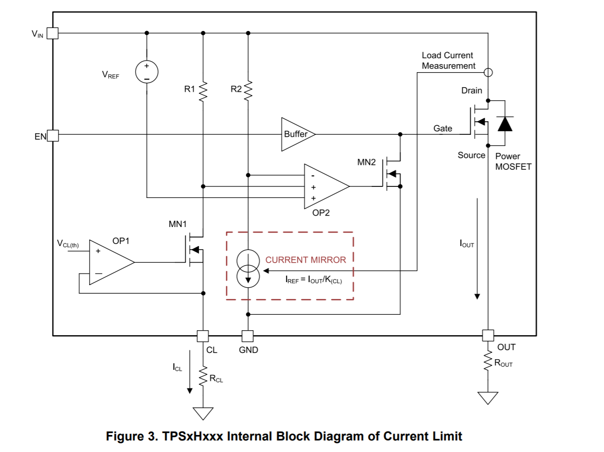
    The current limit circuitry uses an analog current mirror with a comparator to determine if the current limit has tripped. This is described in detail in the 3.1 Basic Implementation for TPSxHxxx Devices section of the following application note:

    https://www.ti.com/lit/slva859

    Specifically this diagram will be of some interest on how the current limit operates on the TPS1H100: