This thread has been locked.

If you have a related question, please click the "Ask a related question" button in the top right corner. The newly created question will be automatically linked to this question.

UCC27324: IC Max. operating current

Part Number: UCC27324
Other Parts Discussed in Thread: UCC27201, UCC27282

Hello team,

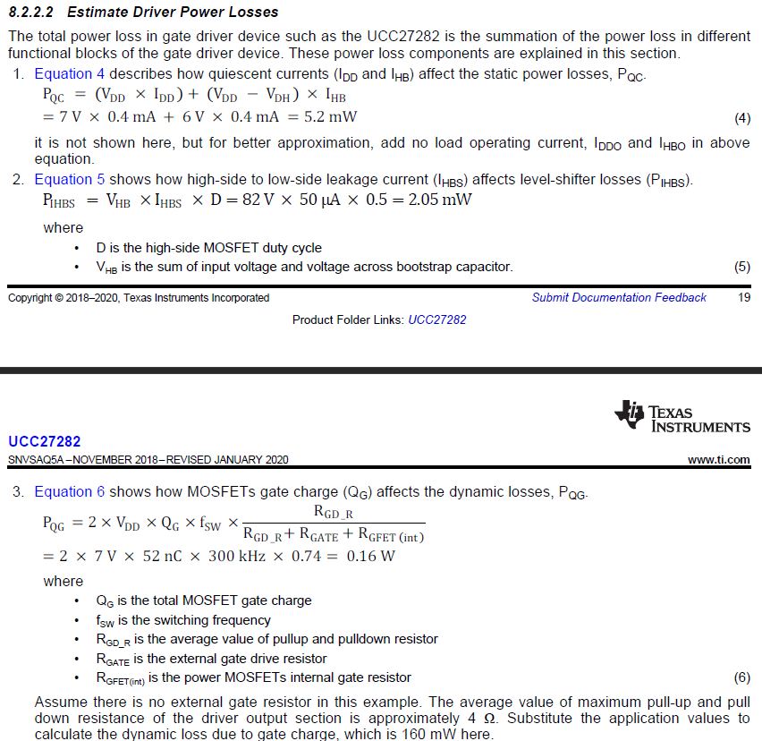
I'd like to know IC's max. operating current to estimate IC's power consumption during operating.

I believe 'static operating current' found in DS means quiescent current, but I cannot find 'operating current'.

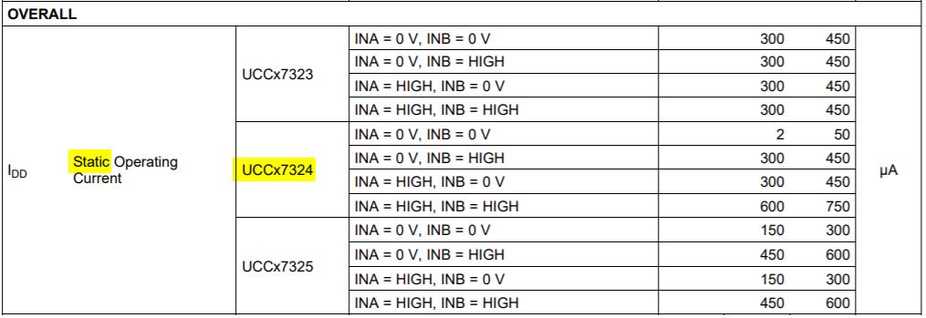
As a note, when it comes to UCC27201, I can find not only quiescent current but also operating current as below. Could you help me to know the corresponding operating current of UCC27324? 

Thanks a lot!

  • Hello Minkyung,

    For the total operating current of the driver, it will be the static operating current as shown in the table plus the current required to drive the MOSFET Qg.

    For the static current I would determine by the maximum duty cycle since the static current is higher with high inputs. For example for 50% duty cycle use 0.5 x 700uA + 0.5 x 50uA. The current required to drive the MOSFET load is Igd= Fsw x Qg, where Fsw is the switching frequency and Qg is the gate charge total of both OUTA and OUTB MOSFET loads.

    Confirm if this addresses your questions, or you can post additional questions on this thread.

    Regards,

  • Hi Richard,

    Thank you for your clear answer. So total current consumption by IC is static (specified in DS) plus Igd (Fsw x Qg as you said).

    I have one vague point from your answer. The MOSFET's gate is driven by the voltage, not the current. So current at the MOSFET load is consumed by a gate capacitance Qg only for a very short moment of time to charge Qg. I think Fsw*Qg is quite a large current from my understanding. Could you correct me if any misunderstanding here?


    Additionally, I'd like to ask a one more question regarding power dissipation.

    When it comes to the power dissipation calculation from the DS of UCC27282, that you mentioned in the previous thread, https://e2e.ti.com/support/power-management/f/196/p/936948/3461467#3461467, does it still vaild with UCC27324?

    Both devices, UCC27324 and UCC27201/27282, are different devices, LS driver and Half-bridge driver. So I guess internal structure and current/power dissipation may be different. 

    Thank you a lot!

  • Hi Minkyung,

    The current during rise/fall times at the gate quickly charge/discharge the gate capacitance at the peak current rating of the driver, which does not come into the picture when calculating the switching current. This is different from the average current (Qg * Fsw) that the driver is pulling from the VDD supply at steady state (i.e. when the driver is holding the gate high).


    Regarding the driver power dissipation calculation, the UCC27282 datasheet does provide the needed equations.  You will use Equation 4 and Equation 6 (Equation 4 will have a minimal contribution to the overall power dissipation).  Equation 5 will NOT be used because the UCC27324 is a dual low side driver.

    Please refer to section 9.2.2.5 of UCC27524 for detailed calculation of a low-side driver.

    Also, please let us know if this answered your question or again, feel free to post additional questions!

    Thanks,

    Aaron Grgurich

  • Minkyung,

    Sorry about the photo not attaching, here it is below:

    Thanks,

    Aaron Grgurich

  • It's so clear. Thank you so much, Aaron!