Other Parts Discussed in Thread: TPS7H1101-SP, TPS7A4501-SP
Sup y'all,
Here it's me again, your boy Mamad, evaluating the TPS7H1101A-SP models shown below in this thread by using OrCAD PSPice.
I wanted to evaluate the stability by the well-known methods, inserting a capacitor and indicator. After that check the Bode diagram and Nyquist diagram.
My expectation is that they should give me relatively similar results like the results from the DC simulation.
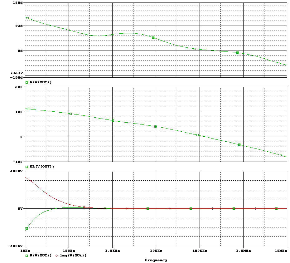
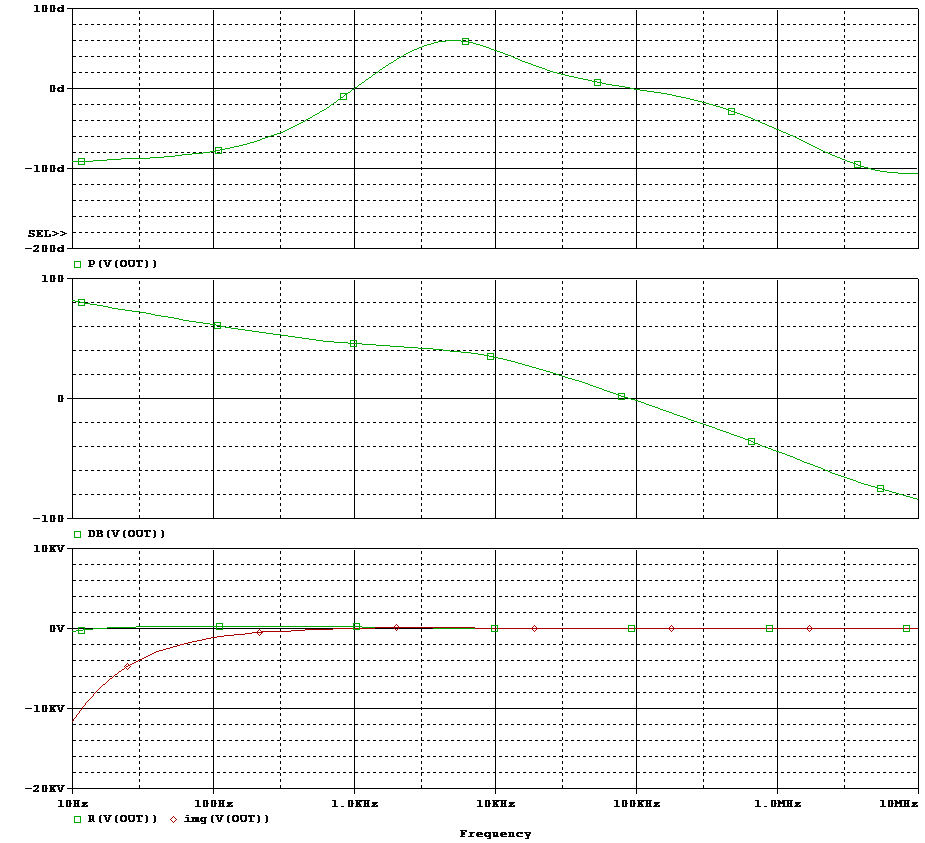
Bode diagram for Phase and Gain, and the frequency response in real and imaginary formats:
| Results based on the TRAN model | Results based on the WCA model |
 |
 |
As you can see the results are very different.
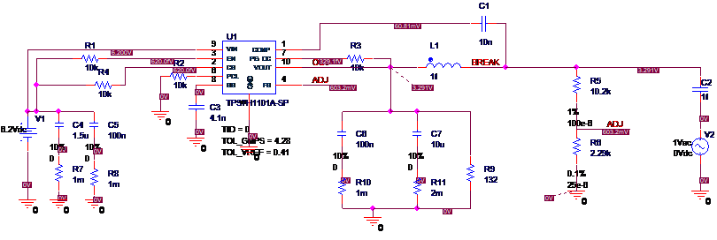
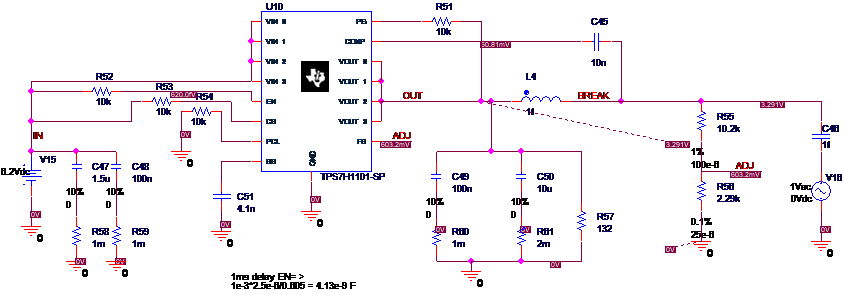
I also show the schematics:
The schematic using the WCA model to evaluate the open-loop gain frequency response:
The schematic using the TRAN model to evaluate the open-loop gain frequency response:
However, the simulated DC operating points are almost the same.
I just wonder why there is a difference? Is it because of TPS7H1101A-SP vs TPS7H1101-SP? I assume the WCA model is the correct one for TPS7H1101A-SP LDO?
I have to know the start up- conditions as well, can I trust the transient simulation based on the TRAN model if I want to use TPS7H1101A-SP LDO?


