This thread has been locked.

If you have a related question, please click the "Ask a related question" button in the top right corner. The newly created question will be automatically linked to this question.

UCC28950: UCC28950 Cycle by cycle current Limiting

Part Number: UCC28950

Dear TI EXperts,

I am using UCC28950 for my charger. My specification is as follows.

Input voltage = 400V 

Output voltage and current = 58.8V/17A(1000W)

CT Ratio=  100T. 

I am working in Voltage mode control with DC blocking capacitor added. I have the following two problems

1. When I Connect RSUM=47K(Connected to VREF)  my cycle by cycle current limit is not triggering even with CT shunt resistor = 82ohm,

2. When I Connect RSUM=12K(Connected to VREF) and CT shunt resistor = between 82 ohm to 22ohm cycle current limit is acting within 1kW

 When I Connect RSUM=12K(Connected to VREF) and CT shunt resistor =22ohm The following events are happening

     2.1 Converter is perfectly working upto 1000W with output voltage regulated to 60V 

     2. 2 From 1000W to 1200W it is in cycle by cycle current limit so that my output voltage is reducing from 60V to 56V 

     2.3 Converter is shutting OFF above 1200W

So i want to trip the converter just above 1000W, and i want to trip it fast. I dont want 200W( which comes around 20%) range of cycle by cycle current limit.

What i need to do for this?

Regards

Aneesh

  • Hello Aneesh

    If you are building a battery charger then you need a CI/CV characteristic. This cannot be achieved if you use only a current sensor on the input line for a few reasons.

    1/ The current limit point is not well defined - typically it will be somewhere between 110% and 130% of the nominal full load point and will vary a bit from PSU to PSU due to unavoidable differences in PSU tolerances - especially magnetizing and output inductances.

    2/ The current limit point will vary as the output voltage changes - that is the current regulation will be relatively poor.

    3/ The current limit point - as seen at the output - will vary as the input voltage varies.

    In summary, the CbC current limit point is intended as a protection mechanism.

    To get a good CI/CV characteristic you need to use a second error amplifier. The usual way to do this is described in the .docx file below and there is a practical example in ref design https://www.ti.com/tool/PMP8740

    /cfs-file/__key/communityserver-discussions-components-files/196/6013.CI_5F00_CV-Characteristic.docx

    Please let me know if I have misunderstood your question -

    Regards
    Colin

  • Dear Collin,

    Thanks for your reply....

    I have CI/CV Loop in my design.I was testing with CV loop alone with CI loop disabled temporally. And my input voltage will not vary it is 400V fixed from the PFC output.

    You said current limit point changes somewhere 110% and 130% .

    1. But will this protect MOSFET against short circuit event?

    2. From 1000W to 1200W converter is in cycle by cycle current limit so that my output voltage is reducing from 60V to 56V

    Is there any way we can reduce this 200W range. I mean i dont want current limiting mode, once over current happened let the converter off. In case if current limiting mode is there i want to reduce the range at which current limiting happens(in my case it is 200W)

    Is there any way we can achieve this by changing RSUM, Soft start capacitor or some other way?

    Regards

    Aneesh

  • Hi Aneesh

    A1/ The Cycle-by-Cycle current limit will protect the MOSFETs from an output short circuit PROVIDED that the MOSFETs are rated to carry the currents that flow between the time when the short is applied and the switching stops - the ILIM time shown in Fig 42 in the Data Sheet. You can shorten the time spent in ILIM by reducing the value of the SS capacitor.

    You also have a possibility to turn the PSU off completely by pulling the SS/EN pin to GND but of course to do this you will need some method to detect the short circuit and a small signal MOSFET to pull the SS/EN pin to ground.

    A2/ If you want a latching shutdown of the converter then you can put a potential divider at the SS/EN pin, use 100k from SS/EN pin to VREF and 180k from SS/EN pin to GND.

    If you need a faster response then you will need some method to detect the over current condition and then use that to turn on a small signal MOSFET from SS/EN to GND. You could set up a comparator to look at the SS/EN voltage and detect when it drops below the 'Normal operating' level (min is 4.2V).

    You will get a faster response if you can use a smaller capacitor at the SS pin - at the expense of a shorter soft start time.

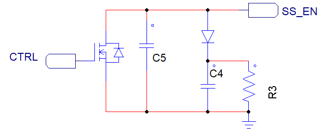
    You could experiment with an arrangement like the one shown below where the SS starting ramp is controlled by the sum of C5 and C4 but the discharge is governed by C5 alone. R3 discharges C4 during the non-switching - hiccup - interval. The MOSFET can be use to enable the controller and to disable it when you detect an over current event. NOTE: using two capacitors in this way is an idea only, I have not implemented or tested it on hardware although I'd have a high degree of confidence that it will work.

    Regards

    Colin