Other Parts Discussed in Thread: SM72295,
Hello,
I am using the SM72442 along with the SM72295 to create a buck only MPPT controller. I modeled my design on the AN-2121 Schematic. I am on the second revision of my schematic which is attached below as ZSCH-0004-RevB. The first schematic had too much noise on the sense lines to operate properly and these issues were alleviated with the second board design.
I will start with a little background on what I am trying to use these products for. I am attempting to use the SM72442 and the SM72295 to create a buck only MPPT solar charge controller that will be used to charge several types of 12V an 24V batteries using our solar panels. The solar panels we manufacture have a Vmp typically between 18V and 21V. Thus, a single panel can be used to charge a single 12V battery in a buck configuration. A primary requirement for this charge controller I am building is that it must accept input voltage (solar) up to 100V (i.e. 4 panels in series) and support an output voltage (battery) of up to 36V (i.e. 2 batteries in series).
In my second design (Rev B) I am getting good, efficient charging for parallel connected panels. I am able to see the characteristic saw tooth waveform on the solar input and the current is steady. I have noticed that in general the voltage at which the controller settles is near 15V and often below despite the fact that our maximum power rating is around 18V or higher. I have not been able to confirm if this is due to incident angle of our panels with respect to the sun or some other factor. In general however, the controller works well for parallel panels on a 12V battery.
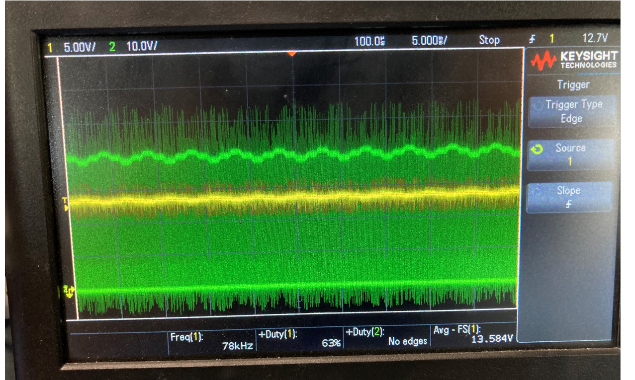
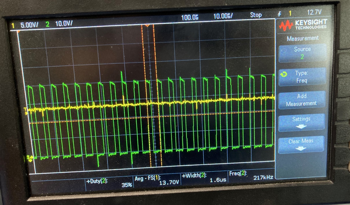
The story is different when I try to connect panels in series and try to charge a 12V battery. Any time the panels are connected in series, the current takes on this very jagged waveform and the voltage has somewhat of an upside down U shaped waveform as shown in the attache images. (In these images, the yellow is the current waveform to the battery obtained by an inductive oscilloscope pickup and the green waveform is the solar voltage. I have observed that as the voltage of the panels increases, the current will essentially stay the same on average to the battery.
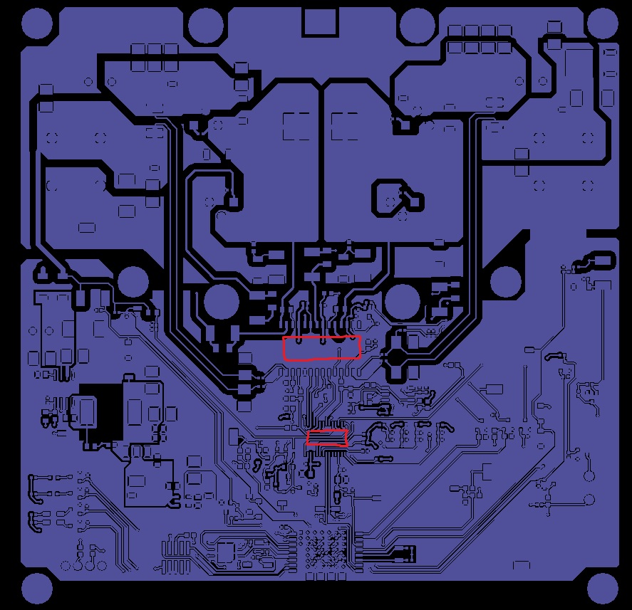
Is this kind of behavior due to noise or something else? As I stated earlier, with my Rev A design, I experienced something similar to this but worse due to noise concerns. I think I have done a much better job with my layout this time by separating power and digital grounds and also putting a ground plane under the current sense traces all the way up to the current sense resistors. I have attached an image of the 4 layers of my PCB design top (purple),second(orange), Third (green), bottom (blue) with the two ICs roughly outlined in red.
I would really appreciate any help you can give me on this design. I am working on my 3rd PCB now but these charging issues are halting my progress and making me consider a different path moving forward. I would really like to use these chip sets for our this controller and our future charge controllers but if this issue cannot be resolved I will be forced to create my own MPPT pwm waveforms that I can adjust on my own.
I have one more question regarding the SM72442. Is there any way to control the duty cycle that the device puts out or any other way to change how it is looking for the maximum power point? I am concerned by the fact that I do not have any kind of control of how the device is searching for the maximum power point. I understand that this is a feature of the device since I don't have to do any control myself but in this situation where it seems as if the device is having difficulty finding the maximum power point it would be helpful to change things on my own and see how the controller reacts.
Please feel free to email me directly if desired at my email below. Also, it appears that there may be some issues with some of the images I am trying to upload. I can send them over email to a service representative if necessary.ZSCH-0004-RevB.pdf
Thank you,
Austin Fox
afox@zampsolar.com